Advanced I/O Controller with Motherboard GLUE Logic
Datasheet
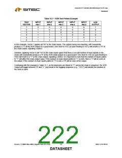
Table 15.1 – XOR Test Pattern Example
INPUT
PIN 1
INPUT
PIN 2
INPUT
PIN 3
INPUT
PIN 4
INPUT
PIN 5
TEST
XOR
VECTOR
OUTPUT
1
2
3
4
5
6
0
1
1
1
1
1
0
0
1
1
1
1
0
0
0
1
1
1
0
0
0
0
1
1
0
0
0
0
0
1
1
0
1
0
1
0
In this example, Vector 1 applies all "0s" to the chain inputs. The outputs being non-inverting, will consistently
produce a "1" at the XOR output on a good board. One short to VCC (or open floating to VCC) will result in a "0" at
the chain output, signaling a defect.
Likewise, applying Vector 6 (all "1s") to the chain inputs (given that there is an odd number of input signals in the
chain) will consistently produce a "0" at the XOR chain output on a good board. One short to VSS (or open floating to
VSS) will result in a "1" at the chain output, signaling a defect. It is important to note that the number of inputs pulled
to "1" will affect the chain output value. If the number of chain inputs pulled to "1" is even, then a "1" will be seen at
the output. If the number of chain inputs pulled to "1" is odd, a "0" will be seen at the output.
Continuing with the example in Table 15.1, as the input pins are driven to "1" across the chain in sequence, the XOR
Output will toggle between "0" and "1." Any break in the toggling sequence (e.g., "1011") will identify the location of
the short or open.
Revision 1.8 SMSC/Non-SMSC Register Sets (02-24-05)
222
SMSC LPC47M182
DATASHEET

 SMSC [ SMSC CORPORATION ]