Advanced I/O Controller with Motherboard GLUE Logic
Datasheet
Chapter 15 Board Test Mode
Board level testing is implemented with an XOR Chain. The XOR chain testing allows motherboard manufacturers to
check component connectivity (e.g., opens and shorts to VCC or GND).
The TEST_EN pin is used as a strap pin to enter test mode. This pin has an internal 30 µA pull-down resistor to VSS.
An external 10 kohm pull-up to V_3P3_STBY is used to put the device in test mode.
Both VCC and VTR supplies are required for the device to operate properly in test mode.
The part enters board test (XOR-chain) mode when the TEST_EN pin is brought high. The part remains in test mode
while TEST_EN is high. Bringing TEST_EN low will exit test mode.
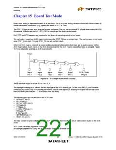
When the XOR chain is entered, all output and bi-directional buffers within that chain are tri-stated, except for the
XOR chain output. Every signal in the XOR chain (except for the XOR chain’s output) functions as an input. Figure
15.1 is a schematic example of XOR chain circuitry.
VCC3
XOR Chain
Output
Input
Pin 1
Input
Pin 2
Input
Pin 3
Input
Pin 4
Input
Pin 5
Figure 15.1 – Example XOR Chain Circuitry
The XOR chain output is on pin 30, nDTR1/XOR.
The input pin ordering is as follows: the first input pin in the XOR chain is pin 1 of the chip (MCLK), and the order
continues around the chip in increasing pin number order to end at pin 128, skipping those pins that are excluded
from the chain (note that pin 117 is excluded from the chain).
The following pins are excluded from the XOR chain.
nRSMRST pin (1)
REF5V pin (1)
REF5V_STBY pin (1)
VCC pins (5)
VTR pins (4)
V_5P0_STBY pin (1)
VSS pins (7)
F_CAP pin (1)
nDTR1/XOR pin (1)
TEST_EN pin (1)
The total number of pins excluded from the XOR chain is 23; therefore there are an odd number of pins in the XOR
chain.
XOR Chain Testability Algorithm Example
An example algorithm for using the XOR chain for board test is shown below.
SMSC LPC47M182
221
Revision 1.8 SMSC/Non-SMSC Register Sets (02-24-05)
DATASHEET

 SMSC [ SMSC CORPORATION ]