Advanced I/O Controller with Motherboard GLUE Logic
Datasheet
BUFFER
NAME
PWR
WELL
NAME
PIN#
DESCRIPTION
NOTES
(NOTE 1)
(NOTE 2)
(NOTE 3)
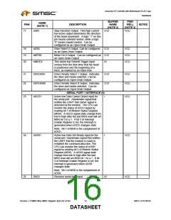
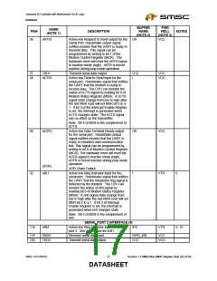
26
nRTS1
Active low Request to Send output for the O8
Serial Port. Handshake output signal
notifies modem that the UART is ready to
transmit data. This signal can be
VCC
programmed by writing to bit 1 of the
Modem Control Register (MCR). The
hardware reset will reset the nRTS signal
to inactive mode (high). nRTS is forced
inactive during loop mode operation.
27
28
TXD1
nCTS1
Transmit serial data output.
O12
I
VCC
VCC
Active low Clear to Send input for the
serial port. Handshake signal that notifies
the UART that the modem is ready to
receive data. The CPU can monitor the
status of nCTS signal by reading bit 4 of
Modem Status Register (MSR). A nCTS
signal state change from low to high after
the last MSR read will set MSR bit 0 to a
1. If bit 3 of the Interrupt Enable Register
is set, the interrupt is generated when
nCTS changes state. The nCTS signal
has no effect on the transmitter.
Note: Bit 4 of MSR is the complement of
nCTS.
30
32
nDTR1
Active low Data Terminal Ready output
for the serial port. Handshake output
signal notifies modem that the UART is
ready to establish data communication
link. This signal can be programmed by
writing to bit 0 of Modem Control Register
(MCR). The hardware reset will reset the
nDTR signal to inactive mode (high).
nDTR is forced inactive during loop mode
operation.
O8
VCC
(XOR)
nRI1
XOR Chain Output.
Active low Ring Indicator input for the
serial port. Handshake signal that notifies
the UART that the telephone ring signal is
detected by the modem. The CPU can
monitor the status of nRI signal by
I
VTR
6
reading bit 6 of Modem Status Register
(MSR). A nRI signal state change from
low to high after the last MSR read will set
MSR bit 2 to a 1. If bit 3 of Interrupt
Enable Register is set, the interrupt is
generated when nRI changes state.
Note: Bit 6 of MSR is the complement of
nRI.
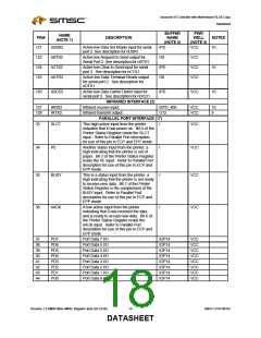
SERIAL PORT 2 INTERFACE (8)
118
nRI2
Active low Ring Indicator input for serial
IPD
VTR
6, 10
port 2. See description for nRI1.
119
120
RXD2
TXD2
Receiver serial data input.
Transmit serial data output.
ISPD_400
O12
VCC
VCC
SMSC LPC47M182
17
Revision 1.8 SMSC/Non-SMSC Register Sets (02-24-05)
DATASHEET

 SMSC [ SMSC CORPORATION ]