Advanced I/O Controller with Motherboard GLUE Logic
Datasheet
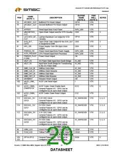
BUFFER
NAME
PWR
WELL
NAME
PIN#
17
DESCRIPTION
NOTES
(NOTE 1)
(NOTE 2)
(NOTE 3)
nDIR
Step Direction Output. This high current
low active output determines the direction
of the head movement. A logic “1” on this
pin means outward motion, while a logic
“0” means inward motion. Can be
O12
VCC
configured as an Open-Drain Output.
18
19
20
nDS0
Drive Select 0 Output. Can be configured
O12
VCC
VCC
VCC
as an Open-Drain Output.
nMTR0
nINDEX
Motor On 0 Output. Can be configured as O12
an Open-Drain Output.
This active low Schmitt Trigger input
senses from the disk drive that the head
is positioned over the beginning of a
track, as marked by an index hole.
IS
21
22
DRVDEN1
DRVDEN0
Drive Density Select 1 Output. Indicates
the drive and media selected. Can be
configured as Open-Drain Output.
Drive Density Select 0 Output. Indicates
the drive and media selected. Can be
configured as Open-Drain Output.
O12
O12
VCC
VCC
SERIAL PORT 1 INTERFACE (8)
23
nDCD1
Active low Data Carrier Detect input for
the serial port. Handshake signal that
notifies the UART that carrier signal is
detected by the modem. The CPU can
monitor the status of nDCD signal by
reading bit 7 of Modem Status Register
(MSR). A nDCD signal state change from
low to high after the last MSR read will set
MSR bit 3 to a 1. If bit 3 of Interrupt
Enable Register is set, the interrupt is
generated when nDCD changes state.
I
VCC
Note: Bit 7 of MSR is the complement of
nDCD.
24
nDSR1
Active low Data Set Ready input for the
serial port. Handshake signal that notifies
the UART that the modem is ready to
establish the communication link. The
CPU can monitor the status of nDSR
signal by reading bit 5 of Modem Status
Register (MSR). A nDSR signal state
change from low to high after the last
MSR read will set MSR bit 1 to a 1. If bit
3 of Interrupt Enable Register is set, the
interrupt is generated when nDSR
changes state.
I
VCC
Note: Bit 5 of MSR is the complement of
nDSR.
25
RXD1
Receiver serial data input.
IS
VCC
Revision 1.8 SMSC/Non-SMSC Register Sets (02-24-05)
16
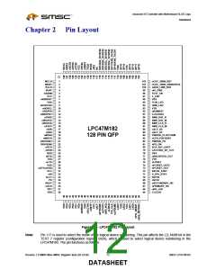
SMSC LPC47M182
DATASHEET

 SMSC [ SMSC CORPORATION ]