Advanced I/O Controller with Motherboard GLUE Logic
Datasheet
9. Chip may modify nWRITE, PDIR and nPDATA in preparation of the next cycle.
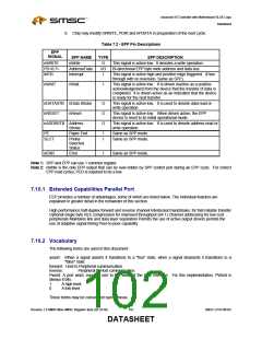
Table 7.2 - EPP Pin Descriptions
EPP
SIGNAL
EPP NAME
nWrite
TYPE
O
EPP DESCRIPTION
This signal is active low. It denotes a write operation.
nWRITE
PD<0:7>
INTR
Address/Data
Interrupt
I/O
I
Bi-directional EPP byte wide address and data bus.
This signal is active high and positive edge triggered. (Pass
through with no inversion, Same as SPP).
nWAIT
nWait
I
This signal is active low. It is driven inactive as a positive
acknowledgement from the device that the transfer of data is
completed. It is driven active as an indication that the device
is ready for the next transfer.
nDATASTB nData Strobe
nRESET nReset
O
O
O
This signal is active low. It is used to denote data read or
write operation.
This signal is active low. When driven active, the EPP
device is reset to its initial operational mode.
nADDRSTB Address
Strobe
This signal is active low. It is used to denote address read or
write operation.
PE
SLCT
Paper End
I
I
Same as SPP mode.
Same as SPP mode.
Printer
Selected
Status
nERR
Error
I
Same as SPP mode.
Note 1: SPP and EPP can use 1 common register.
Note 2: nWrite is the only EPP output that can be over-ridden by SPP control port during an EPP cycle. For correct
EPP read cycles, PCD is required to be a low.
7.10.1 Extended Capabilities Parallel Port
ECP provides a number of advantages, some of which are listed below. The individual features are
explained in greater detail in the remainder of this section.
High performance half-duplex forward and reverse channel Interlocked handshake, for fast reliable transfer
Optional single byte RLE compression for improved throughput (64:1) Channel addressing for low-cost
peripherals Maintains link and data layer separation Permits the use of active output drivers permits the
use of adaptive signal timing Peer-to-peer capability.
7.10.2 Vocabulary
The following terms are used in this document:
assert: When a signal asserts it transitions to a "true" state, when a signal deasserts it transitions to a
"false" state.
forward: Host to Peripheral communication.
reverse:
Peripheral to Host communication
Pword: A port word; equal in size to the width of the LPC interface. For this implementation, PWord is
always 8 bits.
1
0
A high level.
A low level.
These terms may be considered synonymous:
Revision 1.8 SMSC/Non-SMSC Register Sets (02-24-05)
102
SMSC LPC47M182
DATASHEET

 SMSC [ SMSC CORPORATION ]