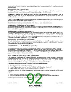
For ACPI compliance the FDD pins that are multiplexed onto the Parallel Port function independently of the state of
the Parallel Port controller. For example, if the FDC is enabled onto the Parallel Port the multiplexed FDD interface
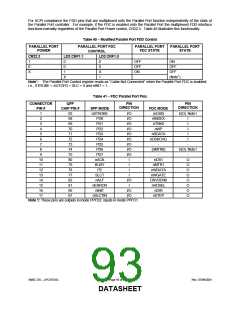
functions normally regardless of the Parallel Port Power control, CR22.3. Table 40 illustrates this functionality.
Table 40 − Modified Parallel Port FDD Control
PARALLEL PORT
POWER
PARALLEL PORT FDC
CONTROL
PARALLEL PORT
FDC STATE
PARALLEL PORT
STATE
CR22.3
LD3:CRF1.1
LD3:CRF1.0
1
0
X
0
0
1
X
0
0
X
1
OFF
OFF
ON
ON
OFF
OFF
(Note1)
Note1: The Parallel Port Control register reads as “Cable Not Connected” when the Parallel Port FDC is enabled;
i.e., STROBE = AUTOFD = SLC = 0 and nINIT = 1.
Table 41 − FDC Parallel Port Pins
CONNECTOR
QFP
PIN
PIN
DIRECTION
DIRECTION
PIN #
1
CHIP PIN #
SPP MODE
nSTROBE
PD0
FDC MODE
(nDS0)
nINDEX
nTRK0
nWP
83
68
69
70
71
72
73
74
75
80
79
78
77
82
81
66
67
I/O
I/O
I/O
I/O
I/O
I/O
I/O
I/O
I/O
I
I/(O) Note1
2
I
3
PD1
I
4
PD2
I
5
PD3
nRDATA
nDSKCHG
-
I
6
PD4
I
7
PD5
-
8
PD6
(nMTR0)
-
I/(O) Note1
9
PD7
-
10
11
12
13
14
15
16
17
nACK
BUSY
PE
nDS1
O
O
O
O
O
O
O
O
I
nMTR1
nWDATA
nWGATE
DRVDEN0
nHDSEL
nDIR
I
SLCT
nALF
I
I/O
I
nERROR
nINIT
nSLCTIN
I/O
I/O
nSTEP
Note 1: These pins are outputs in mode PPFD2, inputs in mode PPFD1.
SMSC DS – LPC47S45x
Page 93 of 259
Rev. 07/09/2001
DATASHEET

 SMSC [ SMSC CORPORATION ]