cycles due to the TC cycle, then a DMA cycle is requested again when there is one byte in the FIFO, and serviceIntr has
been re-enabled.
Programmed I/O Mode or Non-DMA Mode
The ECP or parallel port FIFOs may also be operated using interrupt driven programmed I/O. Software can determine
the writeIntrThreshold, readIntrThreshold, and FIFO depth by accessing the FIFO in Test Mode.
Programmed I/O transfers are to the ecpDFifo at 400H and ecpAFifo at 000H or from the ecpDFifo located at 400H, or
to/from the tFifo at 400H. To use the programmed I/O transfers, the host first sets up the direction and state, sets
dmaEn to 0 and serviceIntr to 0.
The ECP requests programmed I/O transfers from the host by activating the interrupt. The programmed I/O will empty or
fill the FIFO using the appropriate direction and mode.
Note: A threshold of 16 is equivalent to a threshold of 15. These two cases are treated the same.
Programmed I/O - Transfers from the FIFO to the Host
In the reverse direction an interrupt occurs when serviceIntr is 0 and readIntrThreshold bytes are available in the FIFO.
If at this time the FIFO is full it can be emptied completely in a single burst, otherwise readIntrThreshold bytes may be
read from the FIFO in a single burst.
readIntrThreshold =(16-<threshold>) data bytes in FIFO
An interrupt is generated when serviceIntr is 0 and the number of bytes in the FIFO is greater than or equal to (16-
<threshold>). (If the threshold = 12, then the interrupt is set whenever there are 4-16 bytes in the FIFO). The host must
respond to the request by reading data from the FIFO. This process is repeated until the last byte is transferred out of
the FIFO. If at this time the FIFO is full, it can be completely emptied in a single burst, otherwise a minimum of (16-
<threshold>) bytes may be read from the FIFO in a single burst.
Programmed I/O - Transfers from the Host to the FIFO
In the forward direction an interrupt occurs when serviceIntr is 0 and there are writeIntrThreshold or more bytes free in
the FIFO. At this time if the FIFO is empty it can be filled with a single burst before the empty bit needs to be re-read.
Otherwise it may be filled with writeIntrThreshold bytes.
writeIntrThreshold =
(16-<threshold>) free bytes in FIFO
An interrupt is generated when serviceIntr is 0 and the number of bytes in the FIFO is less than or equal to <threshold>.
(If the threshold = 12, then the interrupt is set whenever there are 12 or less bytes of data in the FIFO.) The host must
respond to the request by writing data to the FIFO. If at this time the FIFO is empty, it can be completely filled in a single
burst, otherwise a minimum of (16-<threshold>) bytes may be written to the FIFO in a single burst. This process is
repeated until the last byte is transferred into the FIFO.
6.7.7 PARALLEL PORT FLOPPY DISK CONTROLLER
The Floppy Disk Control signals are available optionally on the parallel port pins. When this mode is selected, the
parallel port is not available. There are two modes of operation, PPFD1 and PPFD2. These modes can be selected
in the Parallel Port Mode Register, as defined in the Parallel Port Mode Register, Logical Device 3, at 0xF1. PPFD1
has only drive 1 on the parallel port pins; PPFD2 has drive 0 and 1 on the parallel port pins.
The following parallel port pins are read as follows by a read of the parallel port register:
1. Data Register (read) = last Data Register (write)
2. Control Register read as "cable not connected" STROBE, AUTOFD and SLC = 0 and nINIT =1
3. Status Register reads: nBUSY = 0, PE = 0, SLCT = 0, nACK = 1, nERR = 1
The following FDC pins are all in the high impedence state when the PPFDC is actually selected by the drive select
register:
1. nWDATA, DENSEL, nHDSEL, nWGATE, nDIR, nSTEP, nDS1, nDS0, nMTR0, nMTR1.
2. If PPFDx is selected, then the parallel port can not be used as a parallel port until "Normal" mode is selected.
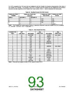
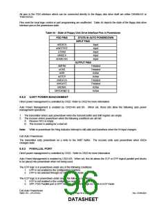
The FDC signals are muxed onto the Parallel Port pins as shown in Table 41.
SMSC DS – LPC47S45x
Page 92 of 259
Rev. 07/09/2001
DATASHEET

 SMSC [ SMSC CORPORATION ]