Interrupts
The interrupts are enabled by serviceIntr in the ecr register.
serviceIntr = 1
serviceIntr = 0
Disables the DMA and all of the service interrupts.
Enables the selected interrupt condition. If the interrupting condition is valid, then the interrupt is
generated immediately when this bit is changed from a 1 to a 0. This can occur during Programmed
I/O if the number of bytes removed or added from/to the FIFO does not cross the threshold.
An interrupt is generated when:
1. For DMA transfers: When serviceIntr is 0, dmaEn is 1 and the DMA TC cycle is received.
2. For Programmed I/O:
a. When serviceIntr is 0, dmaEn is 0, direction is 0 and there are writeIntrThreshold or more free bytes in the
FIFO. Also, an interrupt is generated when serviceIntr is cleared to 0 whenever there are writeIntrThreshold or
more free bytes in the FIFO.
b. When serviceIntr is 0, dmaEn is 0, direction is 1 and there are readIntrThreshold or more bytes in the FIFO.
Also, an interrupt is generated when serviceIntr is cleared to 0 whenever there are readIntrThreshold or more
bytes in the FIFO.
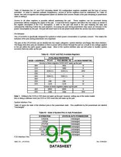
3. When nErrIntrEn is 0 and nFault transitions from high to low or when nErrIntrEn is set from 1 to 0 and nFault is
asserted.
4. When ackIntEn is 1 and the nAck signal transitions from a low to a high.
FIFO Operation
The FIFO threshold is set in the chip configuration registers. All data transfers to or from the parallel port can proceed in
DMA or Programmed I/O (non-DMA) mode as indicated by the selected mode. The FIFO is used by selecting the
Parallel Port FIFO mode or ECP Parallel Port Mode. (FIFO test mode will be addressed separately.) After a reset, the
FIFO is disabled. Each data byte is transferred by a Programmed I/O cycle or DMA cycle depending on the selection of
DMA or Programmed I/O mode.
The following paragraphs detail the operation of the FIFO flow control. In these descriptions, <threshold> ranges from 1
to 16. The parameter FIFOTHR, which the user programs, is one less and ranges from 0 to 15.
A low threshold value (i.e. 2) results in longer periods of time between service requests, but requires faster servicing of
the request for both read and write cases. The host must be very responsive to the service request. This is the desired
case for use with a "fast" system. A high value of threshold (i.e. 12) is used with a "sluggish" system by affording a long
latency period after a service request, but results in more frequent service requests.
DMA Transfers
DMA transfers are always to or from the ecpDFifo, tFifo or CFifo. DMA utilizes the standard PC DMA services. To use
the DMA transfers, the host first sets up the direction and state as in the programmed I/O case. Then it programs the
DMA controller in the host with the desired count and memory address. Lastly it sets dmaEn to 1 and serviceIntr to 0.
The ECP requests DMA transfers from the host by encoding the LDRQ# pin. The DMA will empty or fill the FIFO using
the appropriate direction and mode. When the terminal count in the DMA controller is reached, an interrupt is generated
and serviceIntr is asserted, disabling DMA. In order to prevent possible blocking of refresh requests a DMA cycle shall
not be requested for more than 32 DMA cycles in a row. The FIFO is enabled directly by the host intiating a DMA cycle
for the requested channel, and addresses need not be valid. An interrupt is generated when a TC cycle is received.
(Note: The only way to properly terminate DMA transfers is with a TC cycle.)
DMA may be disabled in the middle of a transfer by first disabling the host DMA controller. Then setting serviceIntr to 1,
followed by setting dmaEn to 0, and waiting for the FIFO to become empty or full. Restarting the DMA is accomplished
by enabling DMA in the host, setting dmaEn to 1, followed by setting serviceIntr to 0.
DMA Mode - Transfers from the FIFO to the Host
(Note: In the reverse mode, the peripheral may not continue to fill the FIFO if it runs out of data to transfer, even if the
chip continues to request more data from the peripheral.)
The ECP requests a DMA cycle whenever there is data in the FIFO. The DMA controller must respond to the request by
reading data from the FIFO. The ECP stop requesting DMA cycles when the FIFO becomes empty or when a TC cycle
is received, indicating that no more data is required. If the ECP stops requesting DMA cycles due to the FIFO going
empty, then a DMA cycle is requested again as soon as there is one byte in the FIFO. If the ECP stops requesting DMA
SMSC DS – LPC47S45x
Page 91 of 259
Rev. 07/09/2001
DATASHEET

 SMSC [ SMSC CORPORATION ]