Fan Control Register
The Fan Control Register is located at 0x58 from base I/O in Logical Device A. The bits are defined below. See the
register description in the “Runtime Registers” section.
Fan Count Divisor, Bits D5-D4
Fan Count Divisor bit in Fan Control Register is used to determine fan tachometer count. The choices for the divisor
are 1, 2, 4 and 8. See “Fan Tachometer Input” section.
Fan Clock Multiplier, Bit D2
The Fan Clock Multiplier bit is used with the Fan Clock Source Select bit in the Fan Control Register and the Fan
Clock Select bit in Fan register to determine the FOUT. When the Fan Clock Multiplier bit = “0”, no clock multiplier is
used. When the Fan Clock Multiplier bit = “1”, the clock speed determined by the Fan Clock Source Select bit is
doubled.
Fan Clock Source Select, Bit D0
The Fan Clock Source Select and the Fan Clock Multiplier bits in the Fan Control register are used with the Fan
Clock Select bit in the Fan register to determine the fan speed FOUT. See Table 61 above.
6.15.2 FAN SPEED MONITORING
The LPC47M45x monitors the speed of the fan by utilizing fan tachometer input signal from fans equipped with
tachometer outputs. There is a signal pin dedicated to the fan tachometer input (pin 57) which is monitored by using
the Fan Tachometer register. This signal, as well as the Fan Tachometer register, are described below (see also
section 6.17.2 Runtime Registers on page 129).
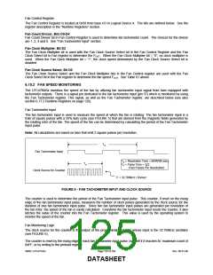
Fan Tachometer Input
The fan tachometer input is used to measure the speed at which the fan is rotating. The fan tachometer input is a
train of square pulses with a 50% duty cycle (see FIGURE 5) that are derived from the magnetic fields generated by
the rotating rotor of the fan. The speed of the fan can be determined by calculating the period of the Fan Tachometer
input pulse.
Note: All calculations are based on fans that emit 2 square pulses per revolution.
TR
Fan Tachometer Input
TR = Revolution Time = 60/RPM (sec)
TP
TP = Pulse Time = T/2
R
(Two Pulses Per Revolution)
Clock Source for Counter
F = 32.786kHz / Divisor
FIGURE 5 − FAN TACHOMETER INPUT AND CLOCK SOURCE
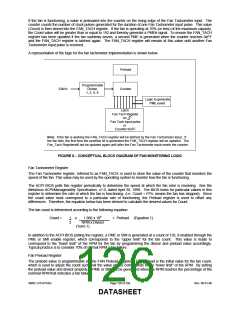
The counter is used to determine the period of the Fan Tachometer input pulse. This counter, if reset on the rising
edge of the fan tachometer input pulse, measures the number of clock pulses generated by the clock source for the
duration of one fan tachometer input pulse. Since two fan tachometer input pulses are generated per revolution of
the fan rotor, the speed of the fan is easily calculated. Everytime the fan tachometer input resets the counter, it also
latches the value of the counter into the Fan Tachometer register. This value is used by the operating system to
monitor the speed of the fan.
Fan Monitoring Logic
The clock source for the counter is the output of the programmable divider whose input is the 32.768kHz oscillator
(see FIGURE 6).
The counter is reset by the rising edge of each fan tachometer input pulse, by itself if it reaches its’ maximum count of
0xFF, or by writing to the preload register.
SMSC LPC47S45x
Page 125 of 259
Rev. 06-01-06
DATASHEET

 SMSC [ SMSC CORPORATION ]