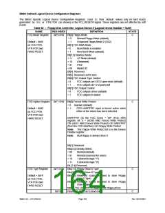
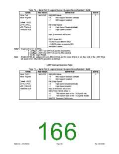
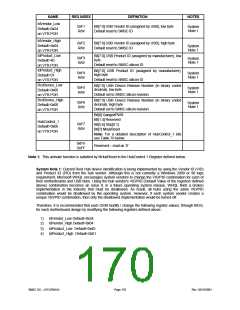
Table 70 – Serial Port 1, Logical Device 4 [Logical Device Number = 0x04]
NAME
Serial Port 1
REG INDEX
0xF0 R/W Bit[0] MIDI Mode
DEFINITION
STATE
C
Mode Register
= 0
= 1
MIDI support disabled (default)
MIDI support enabled
Default = 0x00
on VCC POR,
VTR POR and
HARD RESET
Bit[1] High Speed
= 0
= 1
High Speed Disabled(default)
High Speed Enabled
Bit[6:2] Reserved, set to zero
Bit[7]: Share IRQ
=0 UARTs use different IRQs
=1 UARTs share a common IRQ
See Note 1 below.
Note 1: To properly share and IRQ,
1. Configure UART1 (or UART2) to use the desired IRQ.
2. Configure UART2 (or UART1) to use No IRQ selected.
3. Set the share IRQ bit.
Note: If both UARTs are configured to use different IRQs and the share IRQ bit is set, then both of the UART IRQs
will assert when either UART generates an interrupt.
UART Interrupt Operation Table
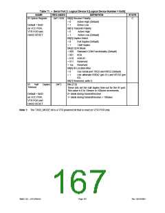
Table 71 – Serial Port 2, Logical Device 5 [Logical Device Number = 0x05]
NAME
Serial Port 2
REG INDEX
0xF0 R/W Bit[0] MIDI Mode
DEFINITION
STATE
C
Mode Register
= 0
= 1
MIDI support disabled (default)
MIDI support enabled
Default = 0x00
on VCC POR,
VTR POR and
HARD RESET
Bit[1] High Speed
= 0
= 1
High Speed disabled(default)
High Speed enabled
Bit[4:2] Reserved, set to zero
Bit[5] TXD2_MODE (Note 1)
=0
=1
The inactive state of the TXD2 pin is low.
The inactive state of the TXD2 pin is tristate.
Bits[7:6] Reserved. Set to zero.
SMSC DS – LPC47M14X
Page 166
Rev. 03/19/2001

 SMSC [ SMSC CORPORATION ]