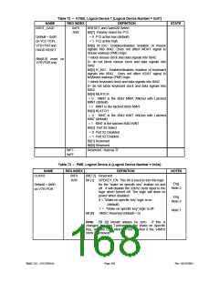
Table 72 – KYBD, Logical Device 7 [Logical Device Number = 0x07]
NAME
KRST_GA20
REG INDEX
0xF0
DEFINITION
KRESET and GateA20 Select
Bit[7] Polarity Select for P12
= 0 P12 active low (default)
= 1 P12 active high
STATE
R/W
Default = 0x00
on VCC POR,
VTR POR and
HARD RESET
Bit[6] M_ISO. Enables/disables isolation of mouse
signals into 8042. Does not affect MDAT signal to
mouse wakeup (PME) logic.
1=block mouse clock and data signals into 8042
Bits[6:5] reset on
VTR POR only
0= do not block mouse clock and data signals into
8042
Bit[5] K_ISO. Enables/disables isolation of keyboard
signals into 8042. Does not affect KDAT signal to
keyboard wakeup (PME) logic.
1=block keyboard clock and data signals into 8042
0= do not block keyboard clock and data signals into
8042
Bit[4] MLATCH
= 0 MINT is the 8042 MINT ANDed with Latched
MINT (default)
= 1 MINT is the latched 8042 MINT
Bit[3] KLATCH
= 0 KINT is the 8042 KINT ANDed with Latched
KINT (default)
= 1 KINT is the latched 8042 KINT
Bit[2] Port 92 Select
= 0 Port 92 Disabled
= 1 Port 92 Enabled
Bit[1] Reserved
Bit[0] Reserved
Reserved - read as ‘0’
0xF1 -
0xFF
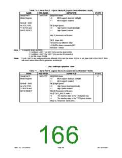
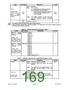
Table 73 – PME, Logical Device A [Logical Device Number = 0x0A]
NAME
CLKI32
REG INDEX
0xF0
DEFINITION
NOTES
Bit[7:2] Reserved
R/W
Bit [1] SPEKEY_EN. This bit is used to turn the logic
Eng.
Note 2
Default = 0x00
on VTR POR
for the “wake on specific key” feature on and
off. It will disable the 32kHz clock input to the
logic when turned off. The logic will draw no
power when disabled.
0 = “Wake on specific key” logic is on
(default)
Eng.
Note 3
1 = “Wake on specific key” logic is off
SMSC Reserved (default = 0)
Note 1
Bit [0]
Note: Bit [0] should always be zero. If this is
changed, the Fan Tachometer, the Wake on Specific
Key, and the LED blink will not function if the 14MHz
clock is removed.
SMSC DS – LPC47M14X
Page 168
Rev. 03/19/2001

 SMSC [ SMSC CORPORATION ]