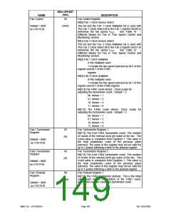
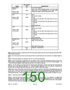
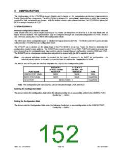
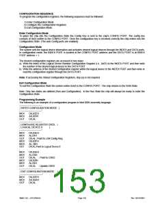
CONFIGURATION SEQUENCE
To program the configuration registers, the following sequence must be followed:
1) Enter Configuration Mode
2) Configure the Configuration Registers
3) Exit Configuration Mode.
Enter Configuration Mode
To place the chip into the Configuration State the Config Key is sent to the chip's CONFIG PORT. The config key
consists of 0x55 written to the CONFIG PORT. Once the configuration key is received correctly the chip enters into the
Configuration State (The auto Config ports are enabled).
Configuration Mode
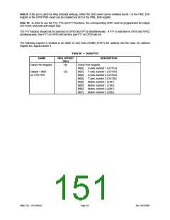
The system sets the logical device information and activates desired logical devices through the INDEX and DATA ports.
In configuration mode, the INDEX PORT is located at the CONFIG PORT address and the DATA PORT is at INDEX
PORT address + 1.
The desired configuration registers are accessed in two steps:
a) Write the index of the Logical Device Number Configuration Register (i.e., 0x07) to the INDEX PORT and then write
the number of the desired logical device to the DATA PORT
b) Write the address of the desired configuration register within the logical device to the INDEX PORT and then write or
read the configuration register through the DATA PORT.
Note: If accessing the Global Configuration Registers, step (a) is not required.
Exit Configuration Mode
To exit the Configuration State the system writes 0xAA to the CONFIG PORT. The chip returns to the RUN State.
Note: Only two states are defined (Run and Configuration). In the Run State the chip will always be ready to enter the
Configuration State.
Programming Example
The following is an example of a configuration program in Intel 8086 assembly language.
;----------------------------.
; ENTER CONFIGURATION MODE |
;----------------------------'
MOV
MOV
OUT
DX,02EH
AX,055H
DX,AL
;----------------------------.
; CONFIGURE REGISTER CRE0, |
; LOGICAL DEVICE 8
;----------------------------'
|
MOV
MOV
OUT
MOV
MOV
OUT
;
DX,02EH
AL,07H
DX,AL ;Point to LD# Config Reg
DX,02FH
AL, 08H
DX,AL;Point to Logical Device 8
MOV
MOV
OUT
MOV
MOV
OUT
DX,02EH
AL,E0H
DX,AL ; Point to CRE0
DX,02fH
AL,02H
DX,AL ; Update CRE0
;-----------------------------.
; EXIT CONFIGURATION MODE
;-----------------------------'
|
MOV
MOV
OUT
DX,02EH
AX,0AAH
DX,AL
SMSC DS – LPC47M14X
Page 153
Rev. 03/19/2001

 SMSC [ SMSC CORPORATION ]