REG OFFSET
(hex)
NAME
Fan Control
DESCRIPTION
58
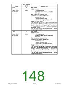
Fan Control Register
Bit[0] Fan 1 Clock Source Select
Default = 0x50
on VTR POR
(R/W)
This bit and the Fan 1 Clock Multiplier bit is used with
The Fan 1 Clock Select bit in the Fan 1 register (0x56) to
determine the fan speed FOUT
.
See Table 57
–
Different Modes for Fan in “Fan Speed Control and
Monitoring” section.
Bit[1] Fan 2 Clock Source Select
This bit and the Fan 2 Clock Multiplier bit is used with
The Fan 2 Clock Select bit in the Fan 2 register (0x57) to
determine the fan speed FOUT
.
See Table 57
–
Different Modes for Fan in “Fan Speed Control and
Monitoring” section.
Bit[2] Fan 1 Clock multiplier
0=No multiplier used
1=Double the fan speed selected by bit 0 of this
register and bit 7 of the FAN1
register
Bit[3] Fan 2 Clock multiplier
0=No multiplier used
1=Double the fan speed selected by bit 1 of this
register and bit 7 of the FAN2 register
Bit[5:4] The FAN1 count divisor. Clock scalar for
adjusting the tachometer count. Default = 2.
00: divisor = 1
01: divisor = 2
10: divisor = 4
11: divisor = 8
Bit[7:6] The FAN2 count divisor. Clock scalar for
adjusting the tachometer count. Default = 2.
00: divisor = 1
01: divisor = 2
10: divisor = 4
11: divisor = 8
Fan Tachometer Register 1
Fan1 Tachometer
Register
59
Bit]7:0] The 8-bit FAN1 tachometer count. The number
of counts of the internal clock per pulse of the fan. The
count value is computed from Equation 1. This value is
the final (maximum) count of the previous pulse
(latched). The value in this register may not be valid for
up to 2 pulses following a write to the preload register.
(R)
Default = 0x00
on VTR POR
Fan2 Tachometer
Register
5A
Fan Tachometer Register 2
Bit[7:0] The 8-bit FAN2 tachometer count. The number
of counts of the internal clock per pulse of the fan. The
count value is computed from Equation 1. This value is
the final (maximum) count of the previous pulse
(latched). The value in this register may not be valid for
up to 2 pulses following a write to the preload register.
(R)
Default = 0x00
on VTR POR
Fan1 Preload
Register
5B
Fan Preload Register 1
Bit[7:0] The FAN1 tachometer preload. This is the initial
value used in the computation of the FAN1 count.
Writing this register resets the tachometer count.
(R/W)
Default = 0x00
on VTR POR
SMSC DS – LPC47M14X
Page 149
Rev. 03/19/2001

 SMSC [ SMSC CORPORATION ]