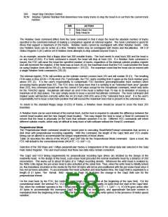
DIR
Head Step Direction Control
RCN Relative Cylinder Number that determines how many tracks to step the head in or out from the current track
number.
DIR
ACTION
0
Step Head Out
1
Step Head In
The Relative Seek command differs from the Seek command in that it steps the head the absolute number of tracks
specified in the command instead of making a comparison against an internal register. The Seek command is good for
drives that support a maximum of 256 tracks. Relative Seeks cannot be overlapped with other Relative Seeks. Only
one Relative Seek can be active at a time. Relative Seeks may be overlapped with Seeks and Recalibrates. Bit 4 of
Status Register 0 (EC) will be set if Relative Seek attempts to step outward beyond Track 0.
As an example, assume that a floppy drive has 300 useable tracks. The host needs to read track 300 and the head is
on any track (0-255). If a Seek command is issued, the head will stop at track 255. If a Relative Seek command is
issued, the FDC will move the head the specified number of tracks, regardless of the internal cylinder position register
(but will increment the register). If the head was on track 40 (d), the maximum track that the FDC could position the head
on using Relative Seek will be 295 (D), the initial track + 255 (D). The maximum count that the head can be moved with
a single Relative Seek command is 255 (D).
The internal register, PCN, will overflow as the cylinder number crosses track 255 and will contain 39 (D). The resulting
PCN value is thus (RCN + PCN) mod 256. Functionally, the FDC starts counting from 0 again as the track number goes
above 255 (D). It is the user's responsibility to compensate FDC functions (precompensation track number) when
accessing tracks greater than 255. The FDC does not keep track that it is working in an "extended track area" (greater
than 255). Any command issued will use the current PCN value except for the Recalibrate command, which only looks
for the TRACK0 signal. Recalibrate will return an error if the head is farther than 79 due to its limitation of issuing a
maximum of 80 step pulses. The user simply needs to issue a second Recalibrate command. The Seek command and
implied seeks will function correctly within the 44 (D) track (299-255) area of the "extended track area". It is the user's
responsibility not to issue a new track position that will exceed the maximum track that is present in the extended area.
To return to the standard floppy range (0-255) of tracks, a Relative Seek should be issued to cross the track 255
boundary.
A Relative Seek can be used instead of the normal Seek, but the host is required to calculate the difference between the
current head location and the new (target) head location. This may require the host to issue a Read ID command to
ensure that the head is physically on the track that software assumes it to be. Different FDC commands will return
different cylinder results, which may be difficult to keep track of with software without the Read ID command.
Perpendicular Mode
The Perpendicular Mode command should be issued prior to executing Read/Write/Format commands that access a
disk drive with perpendicular recording capability. With this command, the length of the Gap2 field and VCO enable
timing can be altered to accommodate the unique requirements of these drives.
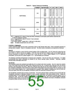
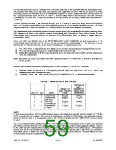
Table 28 describes the effects of the WGATE and GAP bits for the Perpendicular Mode command. Upon a reset, the
FDC will default to the conventional mode (WGATE = 0, GAP = 0).
Selection of the 500 Kbps and 1 Mbps perpendicular modes is independent of the actual data rate selected in the Data
Rate Select Register. The user must ensure that these two data rates remain consistent.
The Gap2 and VCO timing requirements for perpendicular recording type drives are dictated by the design of the
read/write head. In the design of this head, a pre-erase head precedes the normal read/write head by a distance of 200
micrometers. This works out to about 38 bytes at a 1 Mbps recording density. Whenever the write head is enabled by
the Write Gate signal, the pre-erase head is also activated at the same time. Thus, when the write head is initially turned
on, flux transitions recorded on the media for the first 38 bytes will not be preconditioned with the pre-erase head since it
has not yet been activated. To accommodate this head activation and deactivation time, the Gap2 field is expanded to a
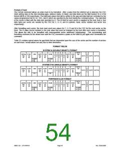
length of 41 bytes. The format field shown on Page 58 illustrates the change in the Gap2 field size for the
perpendicular format.
On the read back by the FDC, the controller must begin synchronization at the beginning of the sync field. For the
conventional mode, the internal PLL VCO is enabled (VCOEN) approximately 24 bytes from the start of the Gap2 field.
But, when the controller operates in the 1 Mbps perpendicular mode (WGATE = 1, GAP = 1), VCOEN goes active after
43 bytes to accommodate the increased Gap2 field size. For both cases, and approximate two-byte cushion is
maintained from the beginning of the sync field for the purposes of avoiding write splices in the presence of motor speed
variation.

 SMSC [ SMSC CORPORATION ]