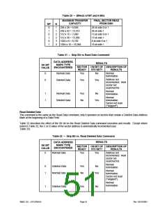
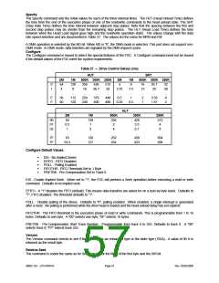
Table 25 – Typical Values for Formatting
FORMAT SECTOR SIZE
N
SC GPL1 GPL2
128
128
512
00 12
00 10
02 08
03 04
04 02
05 01
...
07
10
18
46
C8
C8
09
19
30
87
FF
FF
FM
1024
2048
4096
...
5.25" Drives
256
256
01 12
01 10
02 09
03 04
04 02
05 01
...
0A
20
2A
80
C8
C8
0C
32
50
F0
FF
FF
512*
1024
2048
4096
...
MFM
128
256
512
0
1
2
0F
09
05
07
0F
1B
1B
2A
3A
3.5" Drives
FM
256
512**
1024
1
2
3
0F
09
05
0E
1B
35
36
54
74
MFM
GPL1 = suggested GPL values in Read and Write commands to avoid splice point between data field and
ID field of contiguous sections.
GPL2 = suggested GPL value in Format A Track command.
*PC/AT values (typical)
**PS/2 values (typical). Applies with 1.0 MB and 2.0 MB drives.
Note: All values except sector size are in hex.
CONTROL COMMANDS
Control commands differ from the other commands in that no data transfer takes place. Three commands generate an
interrupt when complete: Read ID, Recalibrate, and Seek. The other control commands do not generate an interrupt.
Read ID
The Read ID command is used to find the present position of the recording heads. The FDC stores the values from the
first ID field it is able to read into its registers. If the FDC does not find an ID address mark on the diskette after the
second occurrence of a pulse on the nINDEX pin, it then sets the IC code in Status Register 0 to "01" (abnormal
termination), sets the MA bit in Status Register 1 to "1", and terminates the command.
The following commands will generate an interrupt upon completion. They do not return any result bytes. It is highly
recommended that control commands be followed by the Sense Interrupt Status command. Otherwise, valuable
interrupt status information will be lost.
Recalibrate
This command causes the read/write head within the FDC to retract to the track 0 position. The FDC clears the contents
of the PCN counter and checks the status of the nTRK0 pin from the FDD. As long as the nTRK0 pin is low, the DIR pin
remains 0 and step pulses are issued. When the nTRK0 pin goes high, the SE bit in Status Register 0 is set to "1" and
the command is terminated. If the nTRK0 pin is still low after 79 step pulses have been issued, the FDC sets the SE and
the EC bits of Status Register 0 to "1" and terminates the command. Disks capable of handling more than 80 tracks per
side may require more than one Recalibrate command to return the head back to physical Track 0.
The Recalibrate command does not have a result phase. The Sense Interrupt Status command must be issued after the
Recalibrate command to effectively terminate it and to provide verification of the head position (PCN). During the
command phase of the recalibrate operation, the FDC is in the BUSY state, but during the execution phase it is in a
NON-BUSY state. At this time, another Recalibrate command may be issued, and in this manner parallel Recalibrate
operations may be done on up to four drives at once. Upon power up, the software must issue a Recalibrate command
to properly initialize all drives and the controller.
SMSC DS – LPC47M14X
Page 55
Rev. 05/02/2000

 SMSC [ SMSC CORPORATION ]