Seek
The read/write head within the drive is moved from track to track under the control of the Seek command. The FDC
compares the PCN, which is the current head position, with the NCN and performs the following operation if there is a
difference:
PCN < NCN: Direction signal to drive set to "1" (step in) and issues step pulses.
PCN > NCN: Direction signal to drive set to "0" (step out) and issues step pulses.
The rate at which step pulses are issued is controlled by SRT (Stepping Rate Time) in the Specify command. After each
step pulse is issued, NCN is compared against PCN, and when NCN = PCN the SE bit in Status Register 0 is set to "1"
and the command is terminated. During the command phase of the seek or recalibrate operation, the FDC is in the
BUSY state, but during the execution phase it is in the NON-BUSY state. At this time, another Seek or Recalibrate
command may be issued, and in this manner, parallel seek operations may be done on up to four drives at once.
Note that if implied seek is not enabled, the read and write commands should be preceded by:
1) Seek command - Step to the proper track
2) Sense Interrupt Status command - Terminate the Seek command
3) Read ID - Verify head is on proper track
4) Issue Read/Write command.
The Seek command does not have a result phase. Therefore, it is highly recommended that the Sense Interrupt Status
command is issued after the Seek command to terminate it and to provide verification of the head position (PCN). The
H bit (Head Address) in ST0 will always return to a "0". When exiting POWERDOWN mode, the FDC clears the PCN
value and the status information to zero. Prior to issuing the POWERDOWN command, it is highly recommended that
the user service all pending interrupts through the Sense Interrupt Status command.
Sense Interrupt Status
An interrupt signal is generated by the FDC for one of the following reasons:
1) Upon entering the Result Phase of:
a. Read Data command
b. Read A Track command
c. Read ID command
d. Read Deleted Data command
e. Write Data command
f. Format A Track command
g. Write Deleted Data command
h. Verify command
2) End of Seek, Relative Seek, or Recalibrate command
The Sense Interrupt Status command resets the interrupt signal and, via the IC code and SE bit of Status Register 0,
identifies the cause of the interrupt.
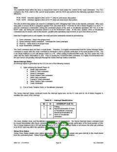
Table 26 – Interrupt Identification
SE
IC
INTERRUPT DUE TO
Polling
0
11
1
00
Normal termination of Seek
or Recalibrate command
Abnormal termination of
Seek or Recalibrate
command
1
01
The Seek, Relative Seek, and Recalibrate commands have no result phase. The Sense Interrupt Status command must
be issued immediately after these commands to terminate them and to provide verification of the head position (PCN).
The H (Head Address) bit in ST0 will always return a "0". If a Sense Interrupt Status is not issued, the drive will continue
to be BUSY and may affect the operation of the next command.
Sense Drive Status
Sense Drive Status obtains drive status information. It has not execution phase and goes directly to the result phase
from the command phase. Status Register 3 contains the drive status information.
SMSC DS – LPC47M14X
Page 56
Rev. 05/02/2000

 SMSC [ SMSC CORPORATION ]