POWER MANAGEMENT
Power management capabilities are provided for the following logical devices: floppy disk, UART 1, UART 2 and the
parallel port. For each logical device, two types of power management are provided: direct powerdown and auto
powerdown.
FDC Power Management
Direct power management is controlled by CR22. Refer to CR22 for more information.
Auto Power Management is enabled by CR23-B0. When set, this bit allows FDC to enter powerdown when all of the
following conditions have been met:
1. The motor enable pins of register 3F2H are inactive (zero).
2. The part must be idle; MSR=80H and INT = 0 (INT may be high even if MSR = 80H due to polling interrupts).
3. The head unload timer must have expired.
4. The Auto powerdown timer (10msec) must have timed out.
An internal timer is initiated as soon as the auto powerdown command is enabled. The part is then powered down when
all the conditions are met.
Disabling the auto powerdown mode cancels the timer and holds the FDC block out of auto powerdown.
DSR From Powerdown
If DSR powerdown is used when the part is in auto powerdown, the DSR powerdown will override the auto powerdown.
However, when the part is awakened from DSR powerdown, the auto powerdown will once again become effective.
Wake Up From Auto Powerdown
If the part enters the powerdown state through the auto powerdown mode, then the part can be awakened by reset or by
appropriate access to certain registers.
If a hardware or software reset is used then the part will go through the normal reset sequence. If the access is through
the selected registers, then the FDC resumes operation as though it was never in powerdown. Besides activating the
nPCI_RESET pin or one of the software reset bits in the DOR or DSR, the following register accesses will wake up the
part:
1. Enabling any one of the motor enable bits in the DOR register (reading the DOR does not awaken the part).
2. A read from the MSR register.
3. A read or write to the Data register.
Once awake, the FDC will reinitiate the auto powerdown timer for 10 ms. The part will powerdown again when all
the powerdown conditions are satisfied.
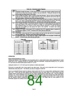
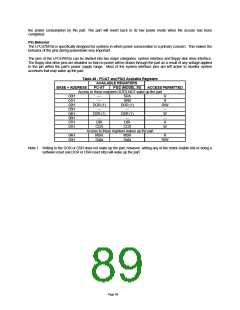
Register Behavior
Table 48 illustrates the AT and PS/2 (including Model 30) configuration registers available and the type of access
permitted. In order to maintain software transparency, access to all the registers must be maintained. As Table 49
shows, two sets of registers are distinguished based on whether their access results in the part remaining in powerdown
state or exiting it.
Access to all other registers is possible without awakening the part. These registers can be accessed during
powerdown without changing the status of the part. A read from these registers will reflect the true status as shown in
the register description in the FDC description. A write to the part will result in the part retaining the data and
subsequently reflecting it when the part awakens. Accessing the part during powerdown may cause an increase in
Page 88

 SMSC [ SMSC CORPORATION ]