LPC INTERFACE
The following sub-sections specify the implementation of the LPC bus.
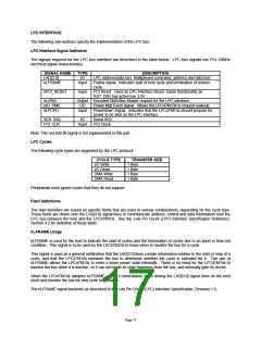
LPC Interface Signal Definition
The signals required for the LPC bus interface are described in the table below. LPC bus signals use PCI 33MHz
electrical signal characteristics.
SIGNAL NAME
LAD[3:0]
nLFRAME
TYPE
I/O
Input
DESCRIPTION
LPC address/data bus. Multiplexed command, address and data bus.
Frame signal. Indicates start of new cycle and termination of broken
cycle
nPCI_RESET
Input
PCI Reset. Used as LPC Interface Reset. Same functionality as
RST_DRV but active low 3.3V.
nLDRQ
Output Encoded DMA/Bus Master request for the LPC interface.
nIO_PME
nLPCPD
OD
Input
Power Mgt Event signal. Allows the LPC47M10x to request wakeup.
Powerdown Signal. Indicates that the LPC47M10x should prepare for
power to be shut on the LPC interface.
SER_IRQ
PCI_CLK
I/O
Input
Serial IRQ.
PCI Clock.
Note: The nCLKRUN signal is not implemented in this part.
LPC Cycles
The following cycle types are supported by the LPC protocol.
CYCLE TYPE
I/O Write
I/O Read
DMA Write
DMA Read
TRANSFER SIZE
1 Byte
1 Byte
1 Byte
1 Byte
Peripherals must ignore cycles that they do not support.
Field Definitions
The data transfers are based on specific fields that are used in various combinations, depending on the cycle type.
These fields are driven onto the LAD[3:0] signal lines to communicate address, control and data information over the
LPC bus between the host and the LPC47M10x. See the Low Pin Count (LPC) Interface Specification Reference,
Section 4.2 for definition of these fields.
nLFRAME Usage
nLFRAME is used by the host to indicate the start of cycles and the termination of cycles due to an abort or time-out
condition. This signal is to be used by the LPC47M10x to know when to monitor the bus for a cycle.
This signal is used as a general notification that the LAD[3:0] lines contain information relative to the start or stop of a
cycle, and that the LPC47M10x monitors the bus to determine whether the cycle is intended for it. The use of
nLFRAME allows the LPC47M10x to enter a lower power state internally. There is no need for the LPC47M10x to
monitor the bus when it is inactive, so it can decouple its state machines from the bus, and internally gate its clocks.
When the LPC47M10x samples nLFRAME active, it immediately stops driving the LAD[3:0] signal lines on the next
clock and monitor the bus for new cycle information.
The nLFRAME signal functions as described in the Low Pin Count (LPC) Interface Specification, Revision 1.0.
Page 17

 SMSC [ SMSC CORPORATION ]