For the KYBD by (refer to the KYBD controller section of this spec).
Note:
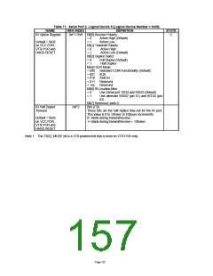
IRQs are disabled if not used/selected by any Logical Device. Refer to Note A.
Note: nSMI must be disabled to use IRQ2.
Note: All IRQ’s are available in Serial IRQ mode.
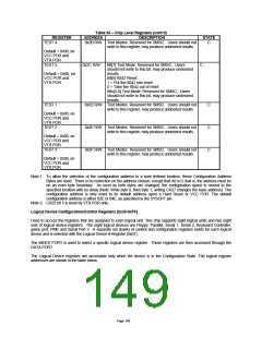
Note 1: The default value of the Primary Interrupt Select register for logical device 0 is 0x06.
Table 67 - DMA Channel Select Configuration Register Description
NAME
DMA Channel
Select
REG INDEX
0x74 (R/W)
DEFINITION
Bits[2:0] select the DMA Channel.
0x00= Reserved
STATE
C
0x01= DMA1
Default=0x02 or
0x04 (Note 1)
on VCC POR,
VTR POR,
0x02= DMA2
0x03= DMA3
0x04-0x07= No DMA active
HARD RESET
and
SOFT RESET
Note:
Note:
A DMA channel is activated by setting the DMA Channel Select register to [0x01-0x03] AND:
For the FDC logical device by setting DMAEN, bit D3 of the Digital Output Register.
For the PP logical device in ECP mode by setting dmaEn, bit D3 of the ecr.
DMA channels are disabled if not used/selected by any Logical Device. Refer to Note A.
Note 1: The default value of the DMA Channel Select register for logical device 0 (FDD) is 0x02 and for logical device
3 and 5 is 0x04.
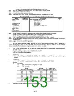
Note A. Logical Device IRQ and DMA Operation
1.
IRQ and DMA Enable and Disable: Any time the IRQ or DMA channel for a logical block is disabled by a
register bit in that logical block, the IRQ and/or DMA channel must be disabled. This is in addition to the IRQ and DMA
channel disabled by the Configuration Registers (active bit or address not valid).
a.
FDC: For the following cases, the IRQ and DMA channel used by the FDC are disabled. Will not respond to
the DMA request.
Digital Output Register (Base+2) bit D3 (DMAEN) set to "0".
The FDC is in power down (disabled).
b.
c.
Serial Ports:
Modem Control Register (MCR) Bit D2 (OUT2) - When OUT2 is a logic "0", the serial port interrupt is
disabled.
Parallel Port:
I.
SPP and EPP modes: Control Port (Base+2) bit D4 (IRQE) set to "0", IRQ is
disabled.
ii.
ECP Mode:
(1)
(2)
(DMA) dmaEn from ecr register. See table.
IRQ - See table.
MODE
IRQ PIN
PDREQ PIN
(FROM ECR REGISTER)
CONTROLLED BY CONTROLLED BY
000
001
010
011
100
101
110
111
PRINTER
SPP
FIFO
ECP
EPP
RES
TEST
CONFIG
IRQE
IRQE
(on)
dmaEn
dmaEn
dmaEn
dmaEn
dmaEn
dmaEn
dmaEn
dmaEn
(on)
IRQE
IRQE
(on)
IRQE
d.
Keyboard Controller: Refer to the KBD section of this spec.
Page 153

 SMSC [ SMSC CORPORATION ]