BIT 4 nTRACK 0
Active low status of the TRK0 disk interface input.
BIT 5 STEP
Active high status of the STEP output disk interface output pin.
BIT 6 nDRV2
This function is not supported. This bit is always read as “1”.
BIT 7 INTERRUPT PENDING
Active high bit indicating the state of the Floppy Disk Interrupt output.
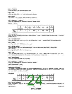
PS/2 Model 30 Mode
7
INT
6
5
4
3
2
1
0
DRQ STEP TRK0 nHDSEL INDX
F/F
WP
nDIR
PENDING
0
RESET
COND.
0
0
N/A
1
N/A
N/A
1
BIT 0 nDIRECTION
Active low status indicating the direction of head movement. A logic "0" indicates inward direction; a logic "1" indicates
outward direction.
BIT 1 WRITE PROTECT
Active high status of the WRITE PROTECT disk interface input. A logic "1" indicates that the disk is write protected.
BIT 2 INDEX
Active high status of the INDEX disk interface input.
BIT 3 nHEAD SELECT
Active low status of the HDSEL disk interface input. A logic "0" selects side 1 and a logic "1" selects side 0.
BIT 4 TRACK 0
Active high status of the TRK0 disk interface input.
BIT 5 STEP
Active high status of the latched STEP disk interface output pin. This bit is latched with the STEP output going active,
and is cleared with a read from the DIR register, or with a hardware or software reset.
BIT 6 DMA REQUEST
Active high status of the DMA request pending.
BIT 7 INTERRUPT PENDING
Active high bit indicating the state of the Floppy Disk Interrupt.
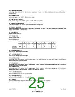
STATUS REGISTER B (SRB)
Address 3F1 READ ONLY
This register is read-only and monitors the state of several disk interface pins in PS/2 andModel 30 modes. The SRB
can be accessed at any time when in PS/2 mode. In the PC/AT mode the data bus pins D0 - D7 are held in a high
impedance state for a read of address 3F1.
PS/2 Mode
7
1
6
1
5
4
3
2
1
0
MOT
EN0
0
DRIVE WDATA RDATA WGATE MOT
SEL0 TOGGLE TOGGLE
0
EN1
0
RESET
COND.
1
1
0
0
0
BIT 0 MOTOR ENABLE 0
Active high status of the MTR0 disk interface output pin. This bit is low after a hardware reset and unaffected by a
software reset.
SMSC LPC47B27x
- 24 -
Rev. 08-10-04
DATASHEET

 SMSC [ SMSC CORPORATION ]