Three Port 10/100 Managed Ethernet Switch with MII
Datasheet
4.2.1.2
nRST Pin Reset
Driving the nRST input pin low initiates a chip-level reset. This event resets all circuitry within the
device. Use of this reset input is optional, but when used, it must be driven for the period of time
specified in Section 14.5.2, "Reset and Configuration Strap Timing," on page 390. Configuration straps
are latched, and the EEPROM Loader is run as a result of this reset.
A nRST pin reset typically takes approximately 760uS, plus additional time (91uS for I2C, 28uS for
Microwire) per byte of data loaded from the EEPROM via the EEPROM Loader. A full EEPROM load
(64KB for I2C, 2KB for Microwire) will complete in approximately 6.0 seconds for I2C EEPROM, and
58mS for Microwire EEPROM.
Note: The nRST pin is pulled-high internally. If unused, this signal can be left unconnected. Do not
rely on internal pull-up resistors to drive signals external to the device.
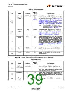
Please refer to Section Table 3.8, "Miscellaneous Pins," on page 39 for a description of the nRST pin.
4.2.2
Multi-Module Resets
Multi-module resets activate multiple internal resets, but do not reset the entire chip. Configuration
straps are not latched upon multi-module resets. A multi-module reset is initiated by assertion of the
following:
Digital Reset (DIGITAL_RST)
Multi-module reset/configuration completion can be determined by first polling the Byte Order Test
Register (BYTE_TEST). The returned data will be invalid until the serial interface resets are complete.
Once the returned data is the correct byte ordering value, the serial interface resets have completed.
The completion of the entire chip-level reset must then be determined by polling the READY bit of the
Hardware Configuration Register (HW_CFG) until it is set. When set, the READY bit indicates that the
reset has completed and the device is ready to be accessed.
With the exception of the Hardware Configuration Register (HW_CFG), Byte Order Test Register
(BYTE_TEST), and Reset Control Register (RESET_CTL), read access to any internal resources is
forbidden while the READY bit is cleared. Writes to any address are invalid until the READY bit is set.
Note: The digital reset does not reset register bits designated as NASR.
4.2.2.1
Digital Reset (DIGITAL_RST)
A digital reset is performed by setting the DIGITAL_RST bit of the Reset Control Register
(RESET_CTL). A digital reset will reset all LAN9313/LAN9313i sub-modules except the Ethernet PHYs
(Port 1 PHY, Port 2 PHY, and Virtual PHY). The EEPROM Loader will automatically run following this
reset. Configuration straps are not latched as a result of a digital reset.
A digital reset typically takes approximately 760uS, plus additional time (91uS for I2C, 28uS for
Microwire) per byte of data loaded from the EEPROM via the EEPROM Loader. A full EEPROM load
(64KB for I2C, 2KB for Microwire) will complete in approximately 6.0 seconds for I2C EEPROM, and
58mS for Microwire EEPROM.
4.2.3
Single-Module Resets
A single-module reset will reset only the specified module. Single-module resets do not latch the
configuration straps or initiate the EEPROM Loader. A single-module reset is initiated by assertion of
the following:
Port 2 PHY Reset
Port 1 PHY Reset
Virtual PHY Reset
SMSC LAN9313/LAN9313i
Revision 1.2 (04-08-08)
DATA4S3HEET

 SMSC [ SMSC CORPORATION ]