Three Port 10/100 Managed Ethernet Switch with MII
Datasheet
Note 3.13 The IS buffer type is valid only during the time specified in Section 14.5.2, "Reset and
Configuration Strap Timing," on page 390 and when in I2C mode.
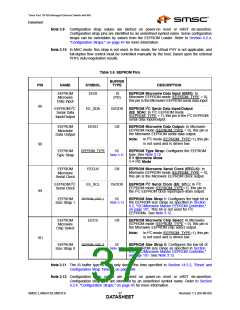
Table 3.7 Serial Management Pins
BUFFER
PIN
NAME
SYMBOL
TYPE
DESCRIPTION
SPI Slave
Serial Data
Input
SI
IS
(PU)
SPI Slave Serial Data Input: In SPI slave mode,
this pin is the SPI serial data input.
Note:
In SMI slave and unmanaged modes, this
pin is unused and pulled-up internally.
67
I2C Slave
Serial Data
Input/Output
(I2C Slave
Mode)
SDA
IS/OD8
I2C Serial Data Input/Output: In I2C slave mode,
this pin is the I2C serial data input/output.
Note:
In SMI slave and unmanaged modes, this
pin is unused and pulled-up internally.
SPI Slave
Serial Data
Output
SO
O8
SPI Slave Serial Data Output: In I2C slave, SMI
slave, and unmanaged modes, this pin is not used
and is driven low.
68
69
SPI Slave
Chip Select
nSCS
IS
(PU)
SPI Slave Chip Select: SPI slave mode chip
select input. When low, the LAN9313/LAN9313i
SPI slave is selected for SPI transfers. When high,
the SPI serial data output (SO) is 3-stated. In I2C
slave, SMI slave, and unmanaged modes, this pin
is not used.
SPI Slave
Serial Clock
SCK
SCL
IS
(PU)
SPI Slave Serial Clock: In SPI slave mode, this
pin is the SPI clock input.
Note:
In SMI slave and unmanaged modes, this
pin is unused and pulled-up internally.
70
I2C Slave
Serial Clock
IS
I2C Slave Serial Clock: In I2C slave mode, this pin
is the I2C clock input.
Note:
In SMI slave and unmanaged modes, this
pin is unused and pulled-up internally.
Note: Refer to Section Chapter 8, "Serial Management," on page 101 for additional information
regarding the serial management configuration and functionality.
Revision 1.2 (04-08-08)
SMSC LAN9313/LAN9313i
DATA3S8HEET

 SMSC [ SMSC CORPORATION ]