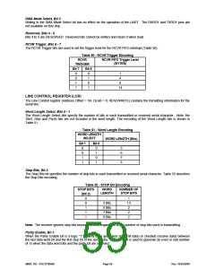
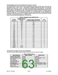
DMA Mode Select, Bit 3
Writing to the DMA Mode Select bit has no effect on the operation of the UART. The RXRDY and TXRDY pins are
not available on this chip.
Reserved, Bits 4 - 5
Bits 4 to 5 are RESERVED. Reserved bits cannot be written and return 0 when read.
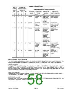
RCVR Trigger, Bits 6 - 7
The RCVR Trigger bits are used to set the trigger level for the RCVR FIFO interrupt (Table 50).
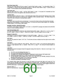
Table 50 - RCVR Trigger Encoding
RCVR
TRIGGER
RCVR FIFO Trigger Level
(BYTES)
Bit 7
0
0
1
1
Bit 6
0
1
0
1
1
4
8
14
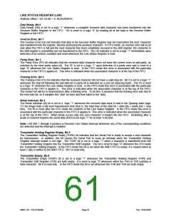
LINE CONTROL REGISTER (LCR)
The Line Control register (Address Offset = 3H, DLAB = 0, READ/WRITE) contains the formatting information for the
serial line.
Word Length Select, Bits 0 - 1
The Word Length Select bits specify the number of bits in each transmitted or received serial character. Note: the
Start, Stop and Parity bits are not included in the word length. The encoding of the Word Length bits is shown in
Table 51.
Table 51 - Word Length Encoding
WORD LENGTH
SELECT
WORD LENGTH (Bits)
Bit 1
Bit 0
0
0
1
1
0
1
0
1
5
6
7
8
Stop Bits, Bit 2
The Stop Bits bit specifies the number of stop bits in each transmitted or received serial character. Table 52 describes
the Stop Bits encoding.
Table 52 - STOP Bit Encoding
STOP BITS
WORD
NUMBER OF
LENGTH
STOP BITS
(Bit 2)
0
0
1
1
1
-
1
1.5
2
2
2
5 Bits
6 Bits
7 Bits
8 Bits
Note: The receiver ignores stop bits beyond the first, regardless of the number of stop bits used in transmitting.
Parity Enable, Bit 3
When the Parity Enable bit is a logic “1” a parity bit is generated (transmit data) or checked (receive data) between
the last data word bit and the first stop bit of the serial data. The parity bit is used to generate an even or odd number
of 1s when the data word bits and the parity bit are summed.
SMSC DS – FDC37N3869
Page 59
Rev. 10/25/2000

 SMSC [ SMSC CORPORATION ]