erase head since it has not yet been activated. To accommodate this head activation and deactivation time, the
Gap2 field is expanded to a length of 41 bytes. The format field shown on page 61 illustrates the change in the
Gap2 field size for the perpendicular format.
On the read back by the FDC, the controller must begin synchronization at the beginning of the sync field. For the
conventional mode, the internal PLL VCO is enabled (VCOEN) approximately 24 bytes from the start of the Gap2
field. But, when the controller operates in the 1 Mbps perpendicular mode (WGATE = 1, GAP = 1), VCOEN goes
active after 43 bytes to accommodate the increased Gap2 field size. For both cases, and approximate two-byte
cushion is maintained from the beginning of the sync field for the purposes of avoiding write splices in the presence of
motor speed variation.
For the Write Data case, the FDC activates Write Gate at the beginning of the sync field under the conventional
mode. The controller then writes a new sync field, data address mark, data field, and CRC as shown in Figure 4. With
the pre-erase head of the perpendicular drive, the write head must be activated in the Gap2 field to insure a proper
write of the new sync field. For the 1 Mbps perpendicular mode (WGATE = 1, GAP = 1), 38 bytes will be written in the
Gap2 space. Since the bit density is proportional to the data rate, 19 bytes will be written in the Gap2 field for the 500
Kbps perpendicular mode (WGATE = 1, GAP =0).
It should be noted that none of the alterations in Gap2 size, VCO timing, or Write Gate timing affect normal program
flow. The information provided here is just for background purposes and is not needed for normal operation. Once
the Perpendicular Mode command is invoked, FDC software behavior from the user standpoint is unchanged.
The perpendicular mode command is enhanced to allow specific drives to be designated Perpendicular recording
drives. This enhancement allows data transfers between Conventional and Perpendicular drives without having to
issue Perpendicular mode commands between the accesses of the different drive types, nor having to change write
pre-compensation values.
When both GAP and WGATE bits of the PERPENDICULAR MODE COMMAND are both programmed to “0”
(Conventional mode), then D0, D1, D2, D3, and D4 can be programmed independently to “1” for that drive to be set
automatically to Perpendicular mode. In this mode the following set of conditions also apply:
1) The GAP2 written to a perpendicular drive during a write operation will depend upon the programmed data rate.
2) The write pre-compensation given to a perpendicular mode drive will be 0ns.
3) For D0-D3 programmed to “0” for conventional mode drives any data written will be at the currently programmed
write pre-compensation.
Note: Bits D0-D3 can only be overwritten when OW is programmed as a “1”.
If either GAP or WGATE is a “1” then D0-D3 are ignored.
Software and hardware resets have the following effect on the PERPENDICULAR MODE COMMAND:
1) “Software” resets (via the DOR or DSR registers) will only clear GAP and WGATE bits to “0”. D0-D3 are
unaffected and retain their previous value.
2) “Hardware” resets will clear all bits (GAP, WGATE and D0-D3) to “0”, i.e. all conventional mode.
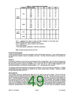
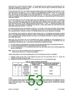
Table 45 - Affects of WGATE and GAP Bits
LENGTH OF GAP2
PORTION OF GAP 2 WRITTEN BY
FORMAT FIELD
WRITE DATA OPERATION
WGATE GAP
MODE
0
0
Conventional
Perpendicular
(500 Kbps)
Reserved
(Conventional)
Perpendicular
(1 Mbps)
22 Bytes
22 Bytes
0 Bytes
0
1
19 Bytes
1
1
0
1
22 Bytes
41 Bytes
0 Bytes
38 Bytes
LOCK
In order to protect systems with long DMA latencies against older application software that can disable the FIFO the
LOCK Command has been added. This command should only be used by the FDC routines, and application software
should refrain from using it. If an application calls for the FIFO to be disabled then the CONFIGURE command
should be used.
SMSC DS – FDC37N3869
Page 53
Rev. 10/25/2000

 SMSC [ SMSC CORPORATION ]