(PCN). The H (Head Address) bit in ST0 will always return a “0”. If a Sense Interrupt Status is not issued, the drive
will continue to be BUSY and may affect the operation of the next command.
SENSE DRIVE STATUS
Sense Drive Status obtains drive status information. It has not execution phase and goes directly to the result phase
from the command phase. Status Register 3 contains the drive status information.
SPECIFY
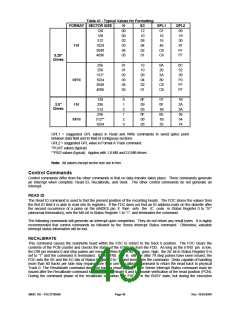
The Specify command sets the initial values for each of the three internal times. The HUT (Head Unload Time)
defines the time from the end of the execution phase of one of the read/write commands to the head unload state.
The SRT (Step Rate Time) defines the time interval between adjacent step pulses. Note that the spacing between
the first and second step pulses may be shorter than the remaining step pulses. The HLT (Head Load Time) defines
the time between when the Head Load signal goes high and the read/write operation starts. The values change
with the data rate speed selection and are documented in
Table 43. The values are the same for MFM and FM.
Table 43 - Drive Control Delays (ms)
HUT
SRT
2M
1M
500K 300K 250K
2M
1M
500K 300K 250K
0
1
..
E
F
64
128
256
426
26.7
..
512
4
8
7.5
..
16
15
..
26.7
32
30
..
4
8
16
32
3.75
..
25
..
..
..
..
..
56
60
112
120
224
240
373
400
448
480
0.5
0.25
1
2
3.33
1.67
4
0.5
1
2
HLT
2M
1M
500K
300K
250K
00
01
02
..
64
0.5
1
128
256
426
3.3
6.7
..
512
1
2
4
2
4
8
..
..
..
.
7F
7F
63
63.5
126
127
252
254
420
423
504
508
The choice of DMA or non-DMA operations is made by the ND bit. When this bit is “1”, the non-DMA mode is
selected, and when ND is “0”, the DMA mode is selected. In DMA mode, data transfers are signaled by the FDRQ
pin. Non-DMA mode uses the RQM bit and the FINT pin to signal data transfers.
CONFIGURE
The Configure command is issued to select the special features of the FDC. A Configure command need not be
issued if the default values of the FDC meet the system requirements.
Configure Default Values:
EIS - No Implied Seeks
EFIFO - FIFO Disabled
POLL - Polling Enabled
FIFOTHR - FIFO Threshold Set to 1 Byte
PRETRK - Pre-Compensation Set to Track 0
EIS - Enable Implied Seek. When set to “1”, the FDC will perform a Seek operation before executing a read or write
command. Defaults to no implied seek.
EFIFO - A “1” disables the FIFO (default). This means data transfers are asked for on a byte-by-byte basis. Defaults
to “1”, FIFO disabled. The threshold defaults to “1”.
POLL - Disable polling of the drives. Defaults to “0”, polling enabled. When enabled, a single interrupt is generated
after a reset. No polling is performed while the drive head is loaded and the head unload delay has not expired.
FIFOTHR - The FIFO threshold in the execution phase of read or write commands. This is programmable from 1 to
16 bytes. Defaults to one byte. A “00” selects one byte; “0F” selects 16 bytes.
SMSC DS – FDC37N3869
Page 51
Rev. 10/25/2000

 SMSC [ SMSC CORPORATION ]