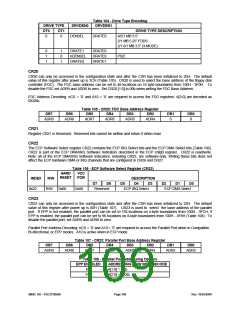
Table 104 - Drive Type Encoding
DRVDEN1
DRIVE TYPE
DRVDEN0
DT0
DT1
DRIVE TYPE DESCRIPTION
0
0
DENSEL
DRATE0
4/2/1 MB 3.5”
2/1 MB 5.25” FDDS
2/1.6/1 MB 3.5” (3-MODE)
0
1
1
1
0
1
DRATE1
nDENSEL
DRATE0
DRATE0
DRATE0
DRATE1
PS/2
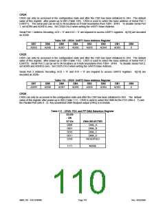
CR20
CR20 can only be accessed in the configuration state and after the CSR has been initialized to 20H. The default
value of this register after power up is 3CH (Table 105). CR20 is used to select the base address of the floppy disk
controller (FDC). The FDC base address can be set to 48 locations on 16 byte boundaries from 100H - 3F0H. To
disable the FDC set ADR9 and ADR8 to zero. Set CR20.[1:0] to 00b when writing the FDC Base Address.
FDC Address Decoding: nCS = ’0’ and A10 = ’0’ are required to access the FDC registers. A[3:0] are decoded as
0XXXb.
Table 105 - CR20: FDC Base Address Register
DB7
DB6
DB5
DB4
DB3
DB2
DB1
DB0
ADR9
ADR8
ADR7
ADR6
ADR5
ADR4
0
0
CR21
Register CR21 is Reserved. Reserved bits cannot be written and return 0 when read.
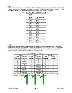
CR22
The ECP Software Select register CR22 contains the ECP IRQ Select bits and the ECP DMA Select bits (Table 106).
CR22 is part of the ECP DMA/IRQ Software Indicators described in the ECP cnfgB register. CR22 is read/write.
Note: all of the ECP DMA/IRQ Software Indicators, including CR22, are software-only. Writing these bits does not
affect the ECP hardware DMA or IRQ channels that are configured in CR26 and CR27.
Table 106 - ECP Software Select Register (CR22)
HARD
VCC
RESET
POR
INDEX
0x22
R/W
DESCRIPTION
D4 D3
ECP IRQ Select
D7
Reserved
D6
D5
D2
D1
D0
R/W
0x00
0x00
ECP DMA Select
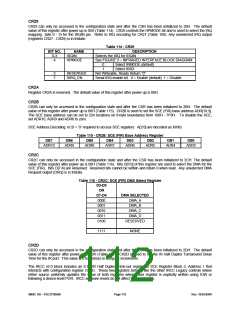
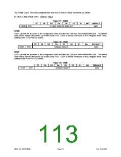
CR23
CR23 can only be accessed in the configuration state and after the CSR has been initialized to 23H. The default
value of this register after power up is 00H (Table 107). CR23 is used to select the base address of the parallel
port. If EPP is not enabled, the parallel port can be set to 192 locations on 4-byte boundaries from 100H - 3FCH; if
EPP is enabled, the parallel port can be set to 96 locations on 8-byte boundaries from 100H - 3F8H (Table 108). To
disable the parallel port, set ADR9 and ADR8 to zero.
Parallel Port Address Decoding: nCS = ’0’ and A10 = ’0’ are required to access the Parallel Port when in Compatible,
Bi-directional, or EPP modes. A10 is active when in ECP mode.
Table 107 - CR23: Parallel Port Base Address Register
DB7
DB6
DB5
DB4
DB3
DB2
DB1
DB0
ADR9
ADR8
ADR7
ADR6
ADR5
ADR4
ADR3
ADR2
Table 108 - Parallel Port Addressing Options
EPP ENABLED
ADDRESSING (LOW BITS) DECODE
A[1:0] = XXb
No
Yes
A[2:0] = XXXb
SMSC DS – FDC37N3869
Page 109
Rev. 10/25/2000

 SMSC [ SMSC CORPORATION ]