CR24
CR24 can only be accessed in the configuration state and after the CSR has been initialized to 24H. The default
value of this register after power up is 00H (Table 109). CR24 is used to select the base address of Serial Port 1
(UART1). The serial port can be set to 96 locations on 8-byte boundaries from 100H - 3F8H. To disable Serial Port
1, set ADR9 and ADR8 to zero. Set CR24.0 to 0 when writing the UART1 Base Address.
Serial Port 1 Address Decoding: nCS = ’0’ and A10 = ’0’ are required to access UART1 registers. A[2:0] are decoded
as XXXb.
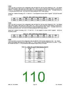
Table 109 - CR24: UART1 Base Address Register
DB7
DB6
DB5
DB4
DB3
DB2
DB1
DB0
ADR9
ADR8
ADR7
ADR6
ADR5
ADR4
ADR3
0
CR25
CR25 can only be accessed in the configuration state and after the CSR has been initialized to 25H. The default
value of this register after power up is 00H (Table 110). CR25 is used to select the base address of Serial Port 2
(UART2). Serial Port 2 can be set to 96 locations on 8-byte boundaries from 100H - 3F8H. To disable Serial Port 2,
set ADR9 and ADR8 to zero. Set CR25.0 to 0 when writing the UART2 Base Address.
Serial Port 2 Address Decoding: nCS = ’0’ and A10 = ’0’ are required to access UART2 registers. A[2:0] are
decoded as XXXb.
Table 110 - CR25: UART2 Base Address Register
DB7
DB6
DB5
DB4
DB3
DB2
DB1
DB0
ADR9
ADR8
ADR7
ADR6
ADR5
ADR4
ADR3
0
CR26
CR26 can only be accessed in the configuration state and after the CSR has been initialized to 26H. The default
value of this register after power up is 00H (Table 111). CR26 is used to select the DMA for the FDC (Bits 4 - 7) and
the Parallel Port (bits 0 - 3). Any unselected DMA Request output (DRQ) is in tristate.
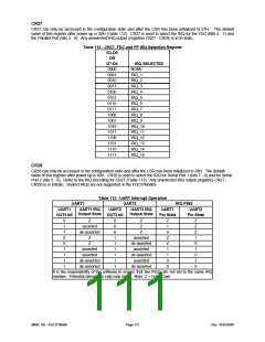
Table 111 - CR26: FDC and PP DMA Selection Register
D3-D0
OR
D7-D4
0000
0001
0010
0011
0100
DMA SELECTED
DMA_A
DMA_B
DMA_C
DMA_D
RESERVED
1111
NONE
SMSC DS – FDC37N3869
Page 110
Rev. 10/25/2000

 SMSC [ SMSC CORPORATION ]