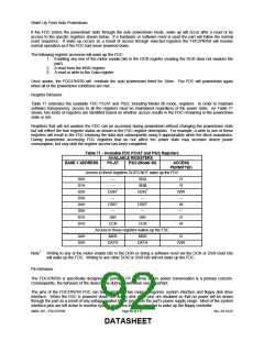
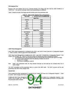
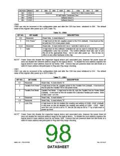
FDD Interface Pins
All pins in the FDD interface that can be connected directly to the floppy disk drive itself are either DISABLED or
TRISTATED. Pins used for local logic control or part programming are unaffected.
Table 73 depicts the state of the floppy disk drive interface pins in the powerdown state.
Table 73 - State of FDC Interface Pins in Powerdown
FDD PINS
STATE IN AUTO POWERDOWN
Input Pins
Input
RDATA
WP
Input
TRK0
Input
INDX
Input
DRV2
DSKCHG
Input
Input
Output Pins
Tristated
Tristated
Active
MOTEN[0:3]
DS[0:3}
DIR
STEP
Active
WRDATA
WE
Tristated
Tristated
Active
HDSEL
DENSEL
DRATE[0:1]
Active
Active
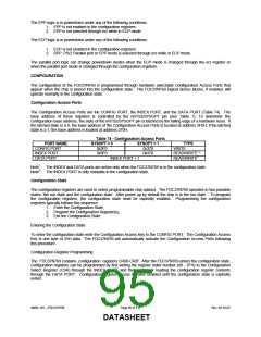
UART Power Management
Direct UART power management is controlled by the UART1 and UART2 Power Down bits in Configuration Register
2. Refer to section CR02 on page 99 for more information.
UART Auto Power Management is enabled by the UART 1 and UART 2 Enable bits in Configuration Register 7 (see
section CR07 on page 102). When set, these bits enable the following auto power management features:
1. The transmitter enters auto powerdown when the transmit buffer and transmit shift register are empty.
2. The receiver enters powerdown when the following conditions are all met:
Receive FIFO is empty
The receiver is waiting for a start bit.
Note:
While in the powerdown state, the Ring Indicator interrupts are still valid and are activated when the RI
inputs change.
The UART transmitters exit the powerdown state on a write to the XMIT buffer. The UART receivers exit the auto
powerdown state when RXDx changes state.
Parallel Port
Direct parallel port power management is controlled by the Parallel Port Power bit in Configuration Register 1. Refer
to section CR01 on page 98 for more information.
Parallel port Auto Power Management is enabled by the Parallel Port Enable bit in Configuration Register 7 (see
section CR07 on page 102). When set, this bit allows the ECP or EPP logical parallel port blocks to be placed into
the powerdown state as follows:
SMSC DS – FDC37N769
Page 94 of 137
Rev. 02-16-07
DATASHEET

 SMSC [ SMSC CORPORATION ]