NAME
REG INDEX
DEFINITION
STATE
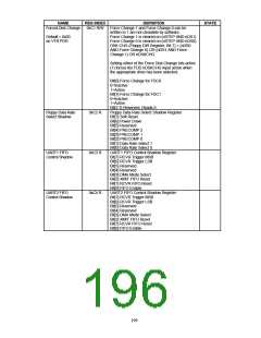
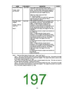
Forced Write Protect
0xC5 R/W
Force Write Protect function forces the FDD
nWRTPRT input active if the FORCE WRTPRT bit is
active. The Force Write Protect function applies to
the nWRTPRT pin in the FDD Interface as well as
the nWRTPRT pin in the Parallel Port FDC.
Default = 0x00
on VTR POR
Bit[0] Force Write Protect bit FDD0
0 = Inactive (Default)
1 = Active “forces the FDD nWRTPRT input active
when the drive has been selected” Note 2
Bit[1:7] Reserved, reads 0.
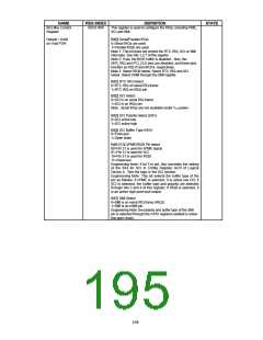
Ring Filter Select
Register
0xC6 R/W
This register is used to select the operation of the
ring indicator on the nRI1, nRI2 and nRING pins.
Bit[0]: 1=Enable detection of pulse train of
frequency 15Hz or higher for 200msec and
generate an active low pulse for its duration to use
as the ring indicator function on nRING pin. The
leading high-to-low edge is the trigger for the ring
indication.
C
Default = 0x00 on
Vbat POR
Note 3
0=Ring indicate function is high-to-low transition on
the nRING pin.
Bit[1]: 1=Enable detection of pulse train of
frequency 15Hz or higher and generate an active
low pulse for its duration to use for 200msec as the
ring indicator function on nRI1 pin. The leading
high-to-low edge is the trigger for the ring
indication.
0=Ring indicate function is high-to-low transition on
the nRI1 pin.
Bit[2]: 1=Enable detection of pulse train of
frequency 15Hz or higher and generate an active
low pulse for its duration to use for 200msec as the
ring indicator function on nRI2 pin. The leading
high-to-low edge is the trigger for the ring
indication.
0=Ring indicate function is high-to-low transition on
the nRI2 pin.
Bits[7:3] Reserved
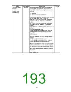
Note 1: There are three types of events Type 1, Type 2 and Type 3.
Type 1: This is an event that comes from a pin or internal signal to the chip. This needs to be edge
detected and latched until cleared by a read of the register. The output of the latch is used to turn
on the power supply through the “or” logic.
Type 2:This is an event that comes from a pin or internal signal to the chip. This does not need to
be edge detected and latched. Cleared at the source.
Type 3: This is an event that comes from a pin or internal signal to the chip. This needs to be edge
detected and latched until cleared by a read of the register. The output of the latch is not used to
turn on the power supply through the “or” logic.
200

 SMSC [ SMSC CORPORATION ]