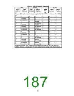
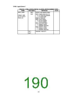
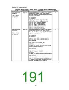
Auxiliary I/O, Logical Device 8
TABLE 83 - AUXILLIARY I/O, LOGICAL DEVICE 8 [LOGICAL DEVICE NUMBER = 0X08]
NAME
Soft Power Enable
Register 1
REG INDEX
0xB0 R/W
DEFINITION
STATE
The following bits are the enables for the wake-up
function of the nPowerOn bit. When enabled,
these bits allow their corresponding function to turn
on power to the system.
C
Default = 0x00
on Vbat POR
1 = ENABLED
0 = DISABLED
Bit[0] SP_RI1: UART 1 Ring Indicator Pin
Bit[1] SP_RI2: UART 2 Ring Indicator Pin
Bit[2] SP_KCLK: Keyboard Clock pin
Bit[3] SP_MCLK: Mouse Clock pin
Bit[4] SP_GPINT1: Group Interrupt 1
Bit[5] SP_GPINT2: Group Interrupt 2
Bit[6] SP_IRRX2: IRRX2 input pin
Bit[7] SP_RTC ALARM: RTC Alarm
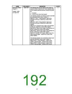
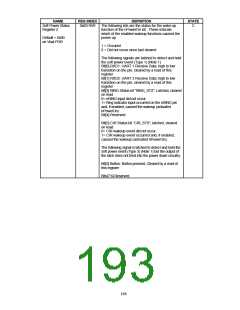
The following bits are the enables for the wake-up
function of the nPowerOn bit. When enabled,
these bits allow their corresponding function to turn
on power to the system.
Soft Power Enable
Register 2
0xB1 R/W
C
Default = 0x80
on Vbat POR
1 = ENABLED
0 = DISABLED
Bit[0] SP_RXD1: UART 1 Receive Data Pin
Bit[1] SP_RXD2: UART 2 Receive Data Pin
Bit[2] Reserved
Bit[3] RING Enable bit “RING_EN”
0=Disable.
1=Enable ring indicator on nRING pin as wakeup
function to activate nPowerOn.
Bit[4] Reserved
Bit[5] CIR Enable bit “CIR_EN”
0=Disable.
1=Enable CIR wakeup event to activate nPowerOn
Bit[6] Reserved
Bit[7] OFF_EN: After power up, this bit defaults to 1,
i.e., enabled. This bit allows the software to enable
or disable the button control of power off.
194

 SMSC [ SMSC CORPORATION ]