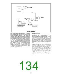
(as above). However, as the oscillator cell will
require an initialization time, either RESET must
be held active for sufficient time to allow the
oscillator to stabilize. Program execution will
resume as above.
Host I/F Data Register
The Input Data and Output Data registers are
each 8 bits wide. A write to this 8 bit register will
load the Keyboard Data Read Buffer, set the OBF
flag and set the KIRQ output if enabled. A read of
this register will read the data from the Keyboard
Data or Command Write Buffer and clear the IBF
flag. Refer to the KIRQ and Status register
descriptions for more information.
INTERRUPTS
The FDC37B78x provides the two 8042 interrupts,
the IBF and the Timer/Counter Overflow.
MEMORY CONFIGURATIONS
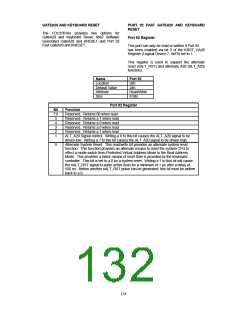
Host I/F Status Register
The FDC37B78x provides 2K of on-chip ROM and
256 bytes of on-chip RAM.
The Status register is 8 bits wide. TABLE 59
shows the contents of the Status register.
Register Definitions
TABLE 59 - STATUS REGISTER
D4 D3
UD C/D
D7
UD
D6
UD
D5
UD
D2
UD
D1
IBF
D0
OBF
132

 SMSC [ SMSC CORPORATION ]