PS/2 mouse products that employ the same type
of interface. To facilitate system expansion, the
FDC37B78x provides four signal pins that may be
used to implement this interface directly for an
external keyboard and mouse.
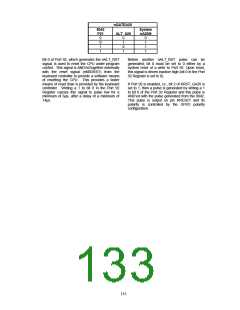
Host-to-CPU Communication
The host system can send both commands and
data to the Input Data register.
The CPU
differentiates between commands and data by
reading the value of Bit 3 of the Status register.
When bit 3 is "1", the CPU interprets the register
contents as a command. When bit 3 is "0", the
CPU interprets the register contents as data.
During a host write operation, bit 3 is set to "1" if
SA2 = 1 or reset to "0" if SA2 = 0.
The FDC37B78x has four high-drive, open-drain
output, bidirectional port pins that can be used for
external serial interfaces, such as ISA external
keyboard and PS/2-type mouse interfaces. They
are KCLK, KDAT, MCLK, and MDAT. P26 is
inverted and output as KCLK. The KCLK pin is
connected to TEST0. P27 is inverted and output
as KDAT. The KDAT pin is connected to P10.
P23 is inverted and output as MCLK. The MCLK
pin is connected to TEST1. P22 is inverted and
output as MDAT. The MDAT pin is connected to
P11. NOTE: External pull-ups may be required.
KIRQ
If "EN FLAGS" has been executed and P24 is set
to a one: the OBF flag is gated onto KIRQ. The
KIRQ signal can be connected to system interrupt
to signify that the FDC37B78x CPU has written to
the output data register via "OUT DBB,A". If P24
is set to a zero, KIRQ is forced low. On power-up,
after a valid RST pulse has been delivered to the
device, KIRQ is reset to 0. KIRQ will normally
reflects the status of writes "DBB". (KIRQ is
normally selected as IRQ1 for keyboard support.)
KEYBOARD POWER MANAGEMENT
The keyboard provides support for two power-
saving modes: soft powerdown mode and hard
powerdown mode. In soft powerdown mode, the
clock to the ALU is stopped but the timer/counter
and interrupts are still active. In hard power down
mode the clock to the 8042 is stopped.
If "EN FLAGS” has not been executed: KIRQ can
be controlled by writing to P24. Writing a zero to
P24 forces KIRQ low; a high forces KIRQ high.
Soft Power Down Mode
MIRQ
If "EN FLAGS" has been executed and P25 is set
to a one:; IBF is inverted and gated onto MIRQ.
The MIRQ signal can be connected to system
interrupt to signify that the FDC37B78x CPU has
read the DBB register.
This mode is entered by executing a HALT
instruction. The execution of program code is
halted until either RESET is driven active or a data
byte is written to the DBBIN register by a master
CPU. If this mode is exited using the interrupt,
and the IBF interrupt is enabled, then program
execution resumes with a CALL to the interrupt
routine, otherwise the next instruction is executed.
If it is exited using RESET then a normal reset
sequence is initiated and program execution starts
from program memory location 0.
If "EN FLAGS” has not been executed, MIRQ is
controlled by P25, Writing a zero to P25 forces
MIRQ low, a high forces MIRQ high. (MIRQ is
normally selected as IRQ12 for mouse support).
Gate A20
A general purpose P21 is used as a software
controlled Gate A20 or user defined output.
Hard Power Down Mode
EXTERNAL
INTERFACE
KEYBOARD
AND
MOUSE
Hard Power Down Mode is entered by executing a
STOP instruction. Disabling the oscillator driver
cell stops the oscillator. When either RESET is
driven active or a data byte is written to the DBBIN
register by a master CPU, this mode will be exited
Industry-standard PC-AT-compatible keyboards
employ a two-wire, bidirectional TTL interface for
data transmission. Several sources also supply
131

 SMSC [ SMSC CORPORATION ]