Fan Control Device with High Frequency PWM Support and Hardware Monitoring Features
Datasheet
The individual fan tach error event bits are defined as follows:
0=disable
1=enable.
See Figure 6.1 Interrupt Controlon page 27.
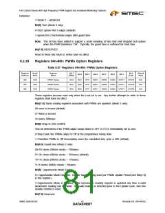
8.2.29
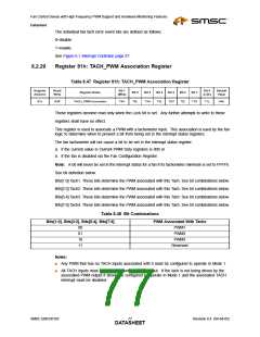
Register 81h: TACH_PWM Association Register
Table 8.47 Register 81h: TACH_PWM Association Register
Register
Address
Read/
Write
Bit 7
Bit 0
Default
Value
Register Name
Bit 6
Bit 5
Bit 4
Bit 3
Bit 2
Bit 1
(MSb)
(LSb)
81h
R/W
TACH_PWM Association
T4H
T4L
T3H
T3L
T2H
T2L
T1H
T1L
A4h
These registers become read only when the Lock bit is set. Any further attempts to write to these
registers shall have no effect.
This register is used to associate a PWM with a tachometer input. This association is used by the fan
logic to determine when to prevent a bit from being set in the interrupt status registers.
The fan tachometer will not cause a bit to be set in the interrupt status register:
a. if the current value in Current PWM Duty registers is 00h or
b. if the fan is disabled via the Fan Configuration Register.
Note: A bit will never be set in the interrupt status for a fan if its tachometer minimum is set to FFFFh.
See bit definition below.
Bits[1:0] Tach1. These bits determine the PWM associated with this Tach. See bit combinations below.
Bits[3:2] Tach2. These bits determine the PWM associated with this Tach. See bit combinations below.
Bits[5:4] Tach3. These bits determine the PWM associated with this Tach. See bit combinations below.
Bits[7:6] Tach4. These bits determine the PWM associated with this Tach. See bit combinations below.
Table 8.48 Bit Combinations
Bits[1:0], Bits[3:2], Bits[5:4], Bits[7:6]
PWM Associated With Tachx
00
01
10
11
PWM1
PWM2
PWM3
Reserved
Notes:
■
Any PWM that has no TACH inputs associated with it must be configured to operate in Mode 1.
■
All TACH inputs must be associated with a PWM output. If the tach is not being driven by the
associated PWM output it should be configured to operate in Mode 1 and the associated TACH
interrupt must be disabled.
SMSC EMC6D103
Revision 0.4 (04-04-05)
DATA7S7HEET

 SMSC [ SMSC CORPORATION ]