Fan Control Device with High Frequency PWM Support and Hardware Monitoring Features
Datasheet
8.2.36
Registers 8Dh: SMSC Test Register
Table 8.55 Registers 8Dh: SMSC Test Register
Register
Address
Read/
Write
Bit 7
Bit 0
Default
Value
Register Name
Bit 6
Bit 5
Bit 4
Bit 3
Bit 2
Bit 1
(MSb)
(LSb)
8Dh
R/W
SMSC Test Register
RES
RES
RES
TST4
TST3
TST2
TST1
TST0
0Eh
This register becomes read only when the Lock bit is set. Any further attempts to write to this register
shall have no effect.
This register must not be written. Writing this register may produce unexpected results.
8.2.37
Registers 8Eh: SMSC Test Register
Table 8.56 Registers 8Eh: SMSC Test Register
Register
Address
Read/
Write
Bit 7
Bit 0
Default
Value
Register Name
Bit 6
Bit 5
Bit 4
Bit 3
Bit 2
Bit 1
(MSb)
(LSb)
8Eh
R
SMSC Test Register
TST7
TST6
TST5
TST4
TST3
TST2
TST1
TST0
N/A
This register is an SMSC Test register.
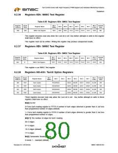
8.2.38
Registers 90h-93h: TachX Option Registers
Register
Address
Read/
Bit 7
Bit 0
Default
Value
Register Name
Bit 6
Bit 5
Bit 4
Bit 3
Bit 2
Bit 1
Write
R/W
R/W
R/W
R/W
(MSb)
(LSb)
90h
91h
92h
93h
Tach1 Option
Tach2 Option
Tach3 Option
Tach4 Option
RESERVED
RESERVED
RESERVED
RESERVED
3EDG
3EDG
3EDG
3EDG
MODE
MODE
MODE
MODE
EDG1
EDG1
EDG1
EDG1
EDG0
EDG0
EDG0
EDG0
SLOW
SLOW
SLOW
SLOW
04h
04h
04h
04h
These registers become read only when the Lock bit is set. Any further attempts to write to these
registers shall have no effect.
Bit[0] SLOW
0=Force tach reading register to FFFEh if number of tach edges detected is greater than 0, but less
than programmed number of edges.(default)
1= Force tach reading register to FFFFh if number of tach edges detected is greater than 0, but less
than programmed number of edges.
Bit[2:1] The number of edges for tach1 reading:
00=2 edges
01=3 edges
10=5 edges (default)
11=9 edges
Bit[3] Tachometer Reading Mode
0=mode 1 – standard (default)
Revision 0.4 (04-04-05)
SMSC EMC6D103
DATA8S0HEET

 SMSC [ SMSC CORPORATION ]