Fan Control Device with High Frequency PWM Support and Hardware Monitoring Features
Datasheet
FFFFh indicates that the fan is not spinning, or the tachometer input is not connected to a valid signal
(This could be triggered by a counter overflow).
These registers are read only – a write to these registers has no effect.
8.2.5
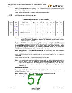
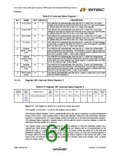
Registers 30-32h: Current PWM Duty
Table 8.8 Registers 30-32h: Current PWM Duty
Register
Address
Read/
Write
Bit 7
Bit 0
Default
Value
Register Name
Bit 6
Bit 5
Bit 4
Bit 3
Bit 2
Bit 1
(MSb)
(LSb)
30h
31h
32h
PWM1 Current Duty Cycle
7
7
7
6
5
4
3
2
1
0
0
0
N/A
N/A
N/A
R/W
(See
Note 8.8)
PWM2 Current Duty Cycle
PWM3 Current Duty Cycle
6
6
5
5
4
4
3
3
2
2
1
1
R/W
(See
Note 8.8)
R/W
(See
Note 8.8)
Note 8.8 These registers are only writable when the associated fan is in manual mode. These
registers become read only when the Lock bit is set. Any further attempts to write to these
registers shall have no effect.
The Current PWM Duty registers store the duty cycle that the chip is currently driving the PWM signals
at. At initial power-on, the duty cycle is 100% and thus, when read, this register will return FFh. After
the Ready/Lock/Start Register Start bit is set, this register and the PWM signals are updated based
on the algorithm described in the Auto Fan Control Operating Mode section and the Ramp Rate
Control logic, unless the associated fan is in manual mode – see below.
Note: When the device is configured for Manual Mode, the Ramp Rate Control logic should be
disabled.
When read, the Current PWM Duty registers return the current PWM duty cycle for the respective
PWM signal.
These registers are read only – a write to these registers has no effect.
Note: If the current PWM duty cycle registers are written while the part is not in manual mode or
when the start bit is zero, the data will be stored in internal registers that will only be active
and observable when the start bit is set and the fan is configured for manual mode. While the
part is not in manual mode and the start bit is zero, the current PWM duty cycle registers will
read back FFh.
Manual Mode (Test Mode)
In manual mode, when the start bit is set to 1 and the lock bit is 0, the current duty cycle registers are
writable to control the PWMs.
Note: When the lock bit is set to 1, the current duty cycle registers are Read-Only.
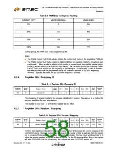
The PWM duty cycle is represented as follows:
SMSC EMC6D103
Revision 0.4 (04-04-05)
DATA5S7HEET

 SMSC [ SMSC CORPORATION ]