Fan Control Device with High Frequency PWM Support and Hardware Monitoring Features
Datasheet
The register is used by application software to identify which device has been implemented in the given
system. Based on this information, software can determine which registers to read from and write to.
Further, application software may use the current stepping to implement work-arounds for bugs found
in a specific silicon stepping. This register is read only – a write to this register has no effect.
8.2.8
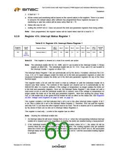
Register 40h: Ready/Lock/Start Monitoring
Table 8.12 Register 40h: Ready/Lock/Start Monitoring
Register
Address
Read/
Bit 7
Bit 0
Default
Value
Register Name
Bit 6
Bit 5
Bit 4
Bit 3
Bit 2
Bit 1
Write
(MSb)
(LSb)
40h
R/W
Ready/Lock/Start
RES
RES
RES
RES
OVRID
READY
LOCK
START
00h
Setting the Lock bit makes the Lock bit read only.
Table 8.13 Ready/Lock/Start Monitoring
R/W DEFAULT DESCRIPTION
When software writes a 1 to this bit, the EMC6D103 enables
BIT
NAME
0
START
R/W
0
monitoring and PWM output control functions based on the limit and
parameter registers. Before this bit is set, the part does not update
register values. Whenever this bit is set to 0, the monitoring and PWM
output control functions are based on the default limits and
parameters, regardless of the current values in the limit and parameter
registers. The EMC6D103 preserves the values currently stored in the
limit and parameter registers when this bit is set or cleared. This bit is
not affected by setting the Lock bit.
Note:
When this bit is 0, all fans are on full 100% duty cycle, i.e.,
PWM pins are high for 255 clocks, low for 1 clock. When this
bit is 0, the part is not monitoring.
1
2
LOCK
R/W
R
0
0
Setting this bit to 1 locks specified limit and parameter registers. Once
this bit is set, limit and parameter registers become read only and will
remain locked until the device is powered off. This register bit becomes
read only once it is set.
READY
The EMC6D103 sets this bit automatically after the part is fully
powered up, has completed the power-up-reset process, and after all
A/D converters are functioning (all bias conditions for the A/Ds have
stabilized and the A/Ds are in operational mode). (Always reads back
‘1’.)
3
OVRID
R/W
R
0
0
If this bit is set to 1, all PWM outputs go to 100% duty cycle regardless
of whether or not the lock bit is set.
4-7
Reserved
Reserved.
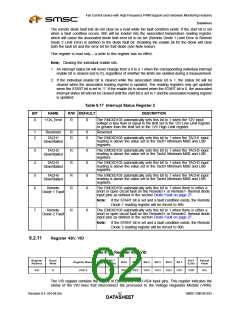
Note: There is a start-up time of up to 82ms for monitoring after the start bit is set to ‘1’, during which
time the reading registers are not valid.
The following summarizes the operation of the part based on the Start bit:
1. If Start bit = '0' then:
a. Fans are set to Full On.
b. No voltage, temperature, or fan tach monitoring is performed. The values in the reading registers
will be N/A (Not Applicable), which means these values will not be considered valid readings until
the Start bit = '1'. The exception to this is the Tachometer reading registers, which always give the
actual reading on the TACH pins.
c. No Status bits are set.
SMSC EMC6D103
Revision 0.4 (04-04-05)
DATA5S9HEET

 SMSC [ SMSC CORPORATION ]