Fan Control Device with High Frequency PWM Support and Hardware Monitoring Features
Datasheet
■
■
■
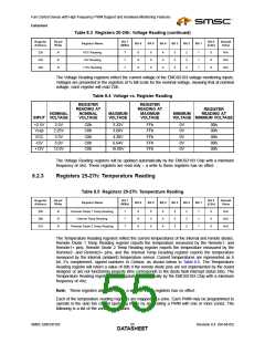
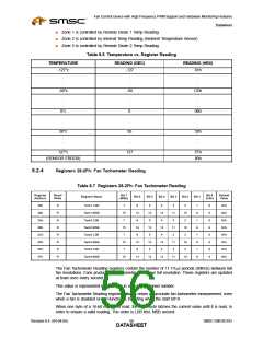
Zone 1 is controlled by Remote Diode 1 Temp Reading
Zone 2 is controlled by Internal Temp Reading (Ambient Temperature Sensor)
Zone 3 is controlled by Remote Diode 2 Temp Reading
Table 8.6 Temperature vs. Register Reading
TEMPERATURE
READING (DEC)
READING (HEX)
-127°c
-127
81h
.
.
.
.
.
.
.
.
.
-50°c
-50
CEh
.
.
.
.
.
.
.
.
.
0°c
0
00h
.
.
.
.
.
.
.
.
.
50°c
50
32h
.
.
.
.
.
.
.
.
.
127°c
(SENSOR ERROR)
127
7Fh
80h
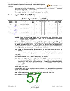
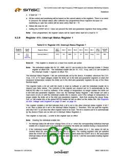
8.2.4
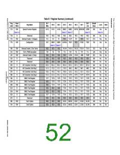
Registers 28-2Fh: Fan Tachometer Reading
Table 8.7 Registers 28-2Fh: Fan Tachometer Reading
Register
Address
Read/
Write
Bit 7
Bit 0
Default
Value
Register Name
Bit 6
Bit 5
Bit 4
Bit 3
Bit 2
Bit 1
(MSb)
(LSb)
28h
29h
2Ah
2Bh
2Ch
2Dh
2Eh
2Fh
R
R
R
R
R
R
R
R
Tach1 LSB
Tach1 MSB
Tach2 LSB
Tach2 MSB
Tach3 LSB
Tach3 MSB
Tach4 LSB
Tach4 MSB
7
6
14
6
5
13
5
4
12
4
3
11
3
2
10
2
1
9
1
9
1
9
1
9
0
8
0
8
0
8
0
8
N/A
N/A
N/A
N/A
N/A
N/A
N/A
N/A
15
7
15
7
14
6
13
5
12
4
11
3
10
2
15
7
14
6
13
5
12
4
11
3
10
2
15
14
13
12
11
10
The Fan Tachometer Reading registers contain the number of 11.111µs periods (90KHz) between full
fan revolutions. Fans produce two tachometer pulses per full revolution. These registers are updated
at least once every second.
This value is represented for each fan in a 16 bit, unsigned number.
The Fan Tachometer Reading registers always return an accurate fan tachometer measurement, even
when a fan is disabled or non-functional, including when the start bit=0.
When one byte of a 16-bit register is read, the other byte latches the current value until it is read, in
order to ensure a valid reading. The order is LSB first, MSB second.
Revision 0.4 (04-04-05)
SMSC EMC6D103
DATA5S6HEET

 SMSC [ SMSC CORPORATION ]