RPM-Based Fan Controller with HW Thermal Shutdown
Datasheet
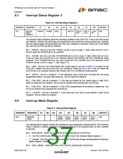
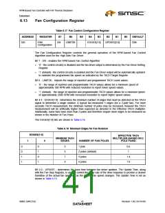
6.7
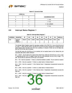
Interrupt Status Register 2
Table 6.10 Interrupt Status Register 2
ADDRESS
REGISTER
B7
B6
B5
B4
B3
B2
B1
B0
DEFAULT
23h
Interrupt
Status
Register 2
PWROK
THERM
HWS
-
WATCH
FAN_S
PIN
FAN_S
TALL
I_SHO
RT
00h
The Interrupt Status Registers report the operating condition of the EMC2102. If any of the bits (except
the PWROK, THERM, and HWS bits) are asserted then the ALERT# pin will be asserted low. Reading
from the status register clears all status bits if the error conditions is removed. If there are no set status
bits, then the ALERT# pin will be released.
Bit 7 - PWROK - this bit is set if the POWER_OK pin is set to a logic ‘1’ state. When this bit is set, it
will not cause the ALERT# pin to be asserted.
Bit 6 - THERM - this bit is set if the THERMTRIP# pin is set to a logic ‘0’ state. When this bit is set,
it will not cause the ALERT# pin to be asserted however will coincide with SYS_SHDN# pin being
asserted. The THERMTRIP# pin can only cause the SYS_SHDN# pin to be asserted if the
POWER_OK pin is set to a logic ‘1’ (see Figure 5.4).
Bit 5 - HWS - this bit is set if the internal HW_SHDN signal is set (see Section 5.7.3) based on the
TRIP_SET voltage and the SHDN_SEL pin conditions. When this bit is set, it will not cause the
ALERT# pin to be asserted however will coincide with SYS_SHDN# pin being asserted.
Bit 3 - WATCH - this bit is asserted ‘1’ if the Watchdog Timer circuit does not detect the fan being
programmed within 4 seconds after power-up. This bit cannot be masked.
Bit 2 - FAN_SPIN - this bit is asserted ‘1’ if the Spin up Routine for Fan cannot detect a valid TACH
within its maximum time window. This bit can be masked from asserting the ALERT# pin.
Bit 1 - FAN_STALL - this bit is asserted ‘1’ if the TACH measurement on fan detects a stalled fan. This
bit can be masked from asserting the ALERT# pin.
Bit 0 - I_SHORT - this bit is asserted ‘1’ if the High Side Fan Driver circuit detects a short circuit
condition. This bit cannot be masked.
6.8
Interrupt Mask Register
Table 6.11 Interrupt Mask Register
ADDRESS
REGISTER
B7
B6
B5
B4
B3
B2
B1
B0
DEFAULT
24h
Interrupt
Mask
-
-
-
SPIN_ STALL_
MASK MASK
EXT3_ EXT2_
MSK MSK
EXT1_ 10h
MSK
The Interrupt Mask Register controls the masking for each temperature channel and the TACH monitor.
When a channel is masked, it will not cause the ALERT# pin to be asserted when an error condition
is detected.
Bit 4 - SPIN_MASK - masks the FAN_SPIN bit from asserting the ALERT# pin.
‘0’ - the FAN_SPIN bit will assert the ALERT# pin if set in the Interrupt Status Register 2.
‘1’ - (default) - the FAN_SPIN bit will not assert the ALERT# pin though will still update the Interrupt
Status Register 2 normally.
Bit 3 - STALL_MASK - masks the FAN_STALL bit from asserting the ALERT# pin.
SMSC EMC2102
Revision 1.95 (10-19-06)
DATA3S7HEET

 SMSC [ SMSC CORPORATION ]