RPM-Based Fan Controller with HW Thermal Shutdown
Datasheet
‘1’ - the External Diode 3 channel high limit will be linked to the SYS_SHDN# pin. If the temperature
exceeds the limit then the SYS_SHDN# pin will be asserted. The ALERT# pin will be asserted
normally.
Bit 4 - SYS2 - enables the high temperature limit for the External Diode 2 channel to trigger the Critical
/ Thermal Shutdown circuitry (see Section 5.7).
‘0’ (default) - the External Diode 2 channel high limit will not be linked to the SYS_SHDN# pin. If
the temperature exceeds the limit, the ALERT# pin will be asserted normally.
‘1’ - the External Diode 2 channel high limit will be linked to the SYS_SHDN# pin. If the temperature
exceeds the limit then the SYS_SHDN# pin will be asserted. The ALERT# pin will be asserted
normally.
Bit 3 - SYS1 - enables the high temperature limit for the External Diode 1 channel to trigger the Critical
/ Thermal Shutdown circuitry (see Section 5.7).
‘0’ (default) - the External Diode 1channel high limit will not be linked to the SYS_SHDN# pin. If
the temperature exceeds the limit, the ALERT# pin will be asserted normally.
‘1’ - the External Diode 1 channel high limit will be linked to the SYS_SHDN# pin. If the temperature
exceeds the limit then the SYS_SHDN# pin will be asserted. The ALERT# pin will be asserted
normally.
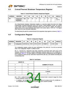
Bit 2 - FORMAT - determines the data format that is displayed in the Temperature Data Registers. The
data format for the Critical Thermal Shutdown Threshold Register will not be changed. If the
temperature data format is changed, the limit register values must be changed to match the newer
format.
‘0’ (default) - the temperature data will be in standard 2’s complement format.
‘1’ - the temperature data will be in offset 2’s complement format.
Bit 0 - LOCK - this bit acts on all registers that are designated SWL. When this bit is set, the locked
registers become read only and cannot be updated.
‘0’ (default) - all SWL registers can be updated normally.
‘1’ - all SWL registers cannot be updated and a hard-reset is required to unlock them.
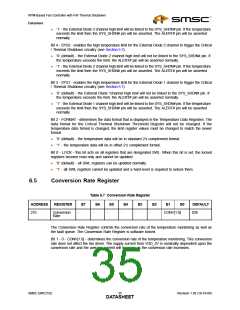
6.5
Conversion Rate Register
Table 6.7 Conversion Rate Register
B6 B5 B4 B3
ADDRESS
REGISTER
B7
B2
B1
B0
DEFAULT
21h
Conversion
Rate
-
-
-
-
-
-
CONV[1:0]
02h
The Conversion Rate Register controls the conversion rate of the temperature monitoring as well as
the fault queue. The Conversion Rate Register is software locked.
Bit 1 - 0 - CONV[1:0] - determines the conversion rate of the temperature monitoring. This conversion
rate does not affect the fan driver. The supply current from VDD_3V is nominally dependent upon the
conversion rate and the average current will increase as the conversion rate increases.
SMSC EMC2102
Revision 1.95 (10-19-06)
DATA3S5HEET

 SMSC [ SMSC CORPORATION ]