RPM-Based Fan Controller with HW Thermal Shutdown
Datasheet
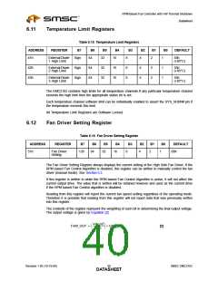
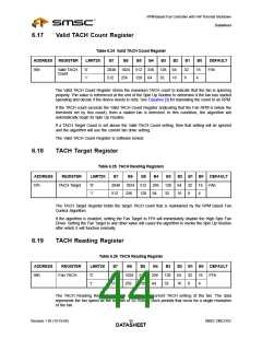
6.11
Temperature Limit Registers
Table 6.15 Temperature Limit Registers
ADDRESS
REGISTER
B7
B6
64
B5
32
B4
16
B3
B2
B1
B0
DEFAULT
41h
External Diode
1 High Limit
Sign
8
8
8
4
2
1
1
1
55h
(+85°C)
42h
43h
External Diode
2 High Limit
Sign
Sign
64
64
32
32
16
16
4
4
2
2
55h
(+85°C)
External Diode
3 High Limit
55h
(+85°C)
The EMC2102 contains high limits for all temperature channels.If any particular temperature channel
exceeds the high limit then the appropriate status bit is set.
Each temperature channel software limit can be individually enabled to assert the SYS_SHDN# pin if
the temperature exceeds this limit.
All Temperature Limit Registers are Software Locked.
6.12
Fan Driver Setting Register
Table 6.16 Fan Driver Setting Register
ADDRESS
REGISTER
B7
B6
64
B5
32
B4
16
B3
B2
B1
B0
DEFAULT
00h
51h
Fan Driver
Setting
128
8
4
2
1
The Fan Driver Setting Register always displays the current setting of the High Side Fan Driver. If the
RPM based Fan Control Algorithm is disabled, this register can be written to manually control the fan
driver (manual mode). See Section 5.2.
If this register is written to while the RPM based Fan Control Algorithm is active, it will not affect the
current output drive. The value that is written will be retained however and used as the current drive
if the RPM based Fan Control algorithm is disabled.
Reading from this register will report the current fan speed setting regardless of the operating mode.
Therefore it is possible that reading from this register will not report data that was previously written
into this register.
The contents of the register represent the weighting of each bit in determining the final output voltage.
The output voltage is given by Equation [2].
VALUE
255
⎛
⎝
⎞
⎠
--------------------
FAN_OUT =
× VDD_5V
[2]
Revision 1.95 (10-19-06)
SMSC EMC2102
DATA4S0HEET

 SMSC [ SMSC CORPORATION ]