5Mbps ARCNET (ANSI 878.1) Controller with 2K x 8 On-Chip RAM
Datasheet
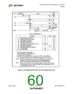
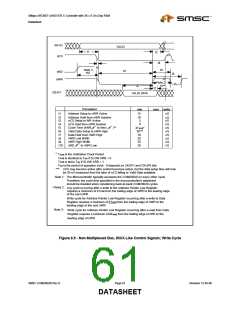
A0-A2
VALID
t1
t2
nCS
t4
t9
t3
Note 3
t8
nRD
t10
t5
nWR
Note 2
t5**
t6
t7
D0-D7
VALID DATA
Parameter
min
max units
t1
Address Setup to nWR Active
15
nS
t2
t3
Address Hold from nWR Inactive
nCS Setup to WR Active
10
5
nS
nS
nCS Hold from nWR Inactive
0
t4
t5
t6
t7
t8
nS
nS
nS
nS
nS
nS
nS
Cycle Time (nWR
to Next
)**
4TARB*
30***
10
20
20
Valid Data Setup to nWR High
Data Hold from nWR High
nWR Low Width
nWR High Width
t9
t10
nRD
to nWR Low
20
*
T
T
T
T
ARB is the Arbitration Clock Period
ARB is identical to Topr if SLOW ARB = 0
ARB is twice Topr if SLOW ARB = 1
opr is the period of operation clock. It depends on CKUP1 and CKUP0 bits
***: nCS may become active after control becomes active, but the data setup time will now
be 30 nS measured from the later of nCS falling or Valid Data available.
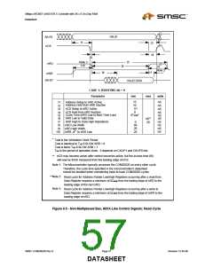
Note 1: The Microcontroller typically accesses the COM20020 on every other cycle.
Therefore, the cycle time specified in the microcontroller's datasheet
should be doubled when considering back-to-back COM20020 cycles.
Note 2:
**
Any cycle occurring after a write to the Address Pointer Low Register
requires a minimum of 4TARB from the trailing edge of nWR to the leading edge
of the next nWR.
Write cycle for Address Pointer Low Register occurring after a write to Data
Register requires a minimum of 5TARB from the trailing edge of nWR to the
leading edge of the next nWR.
Note 3:
Write cycle for Address Pointer Low Register occurring after a read from Data
Register requires a minimum of 5TARB from the trailing edge of nRD to the
leading edge of nWR.
Figure 8.9 - Non-Multiplexed Bus, 80XX-Like Control Signals; Write Cycle
SMSC COM20020I Rev D
Page 61
Revision 12-05-06
DATASHEET

 SMSC [ SMSC CORPORATION ]