5Mbps ARCNET (ANSI 878.1) Controller with 2K x 8 On-Chip RAM
Datasheet
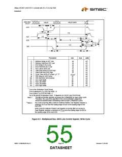
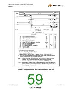
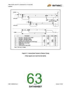
A0-A2
VALID
t1
t2
nCS
t4
t7
t3
DIR
t5
t6
nDS
t10
t11
Note 2
t8
t9
D0-D7
VALID DATA
CASE 1: RBUSTMG bit = 0
Parameter
min
max
units
nS
nS
nS
nS
nS
15
10
5**
0
10
t1
t2
t3
t4
t5
Address Setup to nDS Active
Address Hold from nDS Inactive
nCS Setup to nDS Active
nCS Hold from nDS Inactive
DIR Setup to nDS Active
nS
nS
nS
nS
nS
nS
4TARB*
10
t6
t7
t8
t9
t10
t11
Cycle Time (nDS Low to Next Time Low)
DIR Hold from nDS Inactive
nDS Low to Valid Data
nDS High to Data High Impedence
nDS Low Width
40**
20
0
60
20
nDS High Width
*
T
ARB is the Arbitration Clock Period
TARB is identical to Topr if SLOW ARB = 0
ARB is twice Topr if SLOW ARB = 1
Topr is the period of operation clock. It depends on CKUP1 and CKUP0 bits
T
**
nCS may become active after control becomes active, but the access time (t8) will
now be 45nS measured from the leading edge of nCS.
The Microcontroller typically accesses the COM20020 on every other cycle.
Therefore, the cycle time specified in the microcontroller's datasheet
should be doubled when considering back-to-back COM20020 cycles.
Note 1:
Note 2:
Read cycle for Address Pointer Low/High Registers occurring after an access
to Data Register requires a minimum of 5TARB from the trailing edge of nDS to
the leading edge of the next nDS.
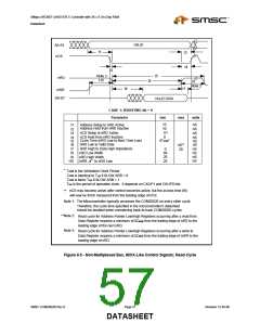
Figure 8.7 - Non-Multiplexed Bus, 68XX-Like Control Signals; Read Cycle
SMSC COM20020I Rev D
Page 59
Revision 12-05-06
DATASHEET

 SMSC [ SMSC CORPORATION ]