Legacy-Free Keyboard/Embedded Controller with SPI and LPC Docking Interface
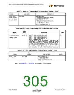
Table 27.8 Serial Port, Logical Device 4 [Logical Device Number = 0x04]
NAME
REG INDEX
0xF0 R/W
DEFINITION
Serial Port 1
Bit[0] MIDI Mode
Mode Register
= 0 MIDI support disabled (default)
= 1 MIDI support enabled
Bit[1] High Speed
Default = 0x00
= 0 High Speed Disabled (default)
= 1 High Speed Enabled
Bit[7:2] Reserved, set to “0”
Table 27.9 RTC, LOGICAL DEVICE 6 [LOGICAL DEVICE NUMBER = 0X06]
REG
NAME
INDEX
DEFINITION
STATE
RTC Mode Register
Default = 0x00
0xF0 R/W
Bit[0] = 1: Lock CMOS RAM 80-9Fh
C
Bit[1] = 1: Lock CMOS RAM A0-BFh
Bit[2] = 1: Lock CMOS RAM C0-DFh
Bit[3] = 1: Lock CMOS RAM E0-FEh
Bit[7:4] Reserved, set to “0”
Once set, bit[3:0] can not be cleared by a write; bits[3:0] are
cleared on VCC2 Power On Reset, VCC2 Power Off, or upon
a Hard Reset (nRESET_OUT asserted). Once lock bits are
set, both the Host and the 8051 are locked out of accessing
the locked locations as long as VCC1 and VCC2 are active.
When VCC2 goes to 0V, the lock bits are cleared and the
8051 can access this RAM while nRESET_OUT is asserted.
Table 27.10 KYBD, Logical Device 7 [Logical Device Number = 0x07]
REG
NAME
KRST_GA20
INDEX
DEFINITION
STATE
0xF0 R/W
Bit[0]: ENAB_P92
= 0: Port 92 Disabled
= 1: Port 92 Enabled
Bit[7:0]: Reserved, set to “0”.
Note: See Section 13.4.4, "GATEA20" for descriptions of these registers.
SMSC LPC47N350
287
Revision 1.1 (01-14-03)
DATASHEET

 SMSC [ SMSC CORPORATION ]