Legacy-Free Keyboard/Embedded Controller with SPI and LPC Docking Interface
10.3
10.4
Docking Procedure
The switching for the Docking LPC interface Docking is controlled by the DLPC SWITCH bit in the
Docking LPC Switch Register described in Section 10.4.2, "Docking LPC Switch Register" below.
When a docking event is detected, the system writes a value of 01h to the Docking LPC Switch Register
connecting the LPC interface to the Docking LPC interface.
The Docking Super I/O will be accessible as any typical LPC device on the LPC bus.
Registers
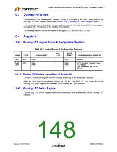
10.4.1 Docking LPC Logical Device C Configuration Registers
Table 10.2 Logical Device C Configuration Registers
VCC1
POR
SOFT
INDEX
TYPE
R/W
R/W
HARD RESET
RESET
CONFIGURATION REGISTER
0x30
0x00
-
-
0x00
Activate
0x60,
0x61
0x00,
0x00
0x00,
0x00
DLPC Runtime Registers Base
I/O Address.
Valid addresses are 0100h –
0FFFh
10.4.1.1 Docking LPC Interface Logical Device C Activate Bit
The DLPC Activate Bit (Logical Device C 0x30[0]) powers up in the deasserted (‘0’) state.
When the DLPC device is deactivated (Activate Bit = 0), the LPC47N350 LPC Host cannot decode the
Docking LPC Switch register and therefore cannot activate the DLPC switches.
10.4.2 Docking LPC Switch Register
The Docking LPC Switch Register controls the connection and disconnection of the Docking LPC
Interface.
Revision 1.1 (01-14-03)
130
SMSC LPC47N350
DATASHEET

 SMSC [ SMSC CORPORATION ]