Legacy-Free Keyboard/Embedded Controller with SPI and LPC Docking Interface
Chapter 10 Hot Plug LPC Docking Interface
10.1
Overview
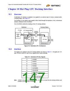
A switchable LPC interface is available to be supplied to an external Super I/O device contained within
a docking station. See Figure 10.1.
The Docking LPC bus signals, when enabled, will be routed through low impedance (10Ω), bi-directional
switches contained in the LPC47N350.
The LPC47N350 controls the enabling of the LPC docking interface.
Notebook
Docking Station
LPC Bus
LPC Docking Switch
Docking
Connector
System
LPC
Master
Control
Register
LPC Host
LPC Host
Dock
Ports
Notebook
Ports
Primary Super I/O
Docking Super I/O
Figure 10.1 Switched LPC Architecture
10.2
Interface
The signals to be switched in the LPC Docking interface are shown in Table 10.1. All signals are 3.3V
only. LPCPD#, LRESET#, and PCICLK signals will be routed externally.
.
Table 10.1 Switched LPC Bus Signals
1)
2)
3)
4)
5)
6)
7)
8)
9)
DLAD[0]
DLAD[1]
DLAD[2]
DLAD[3]
DLFRAME#
DCLKRUN#
DSER_IRQ
DLDRQ#
LDRQ# (See Note)
Note: LDRQ# is not part of the docking interface. DLDRQ# is an input from the docking interface and
LDRQ# is an output from LPC47N350.
SMSC LPC47N350
129
Revision 1.1 (01-14-03)
DATASHEET

 SMSC [ SMSC CORPORATION ]