ST7781
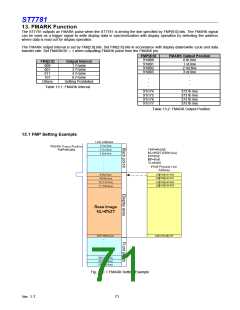
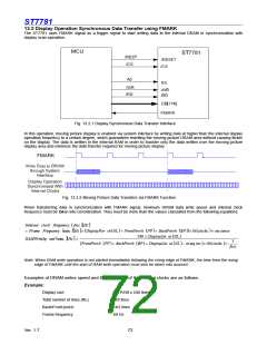
13.2 Display Operation Synchronous Data Transfer using FMARK
The ST7781 uses FMARK signal as a trigger signal to start writing data to the internal DRAM in synchronization with
display scan operation.
Fig. 13.2.1 Display Synchronous Data Transfer Interface
In this operation, moving picture display is enabled via system interface by writing data at higher than the internal display
operation frequency to a certain degree, which guarantees rewriting the moving picture DRAM area without causing flicker
on the display. The data is written in the internal RAM in order to transfer only the data written over the moving picture
display area and minimize the data transfer required for moving picture display.
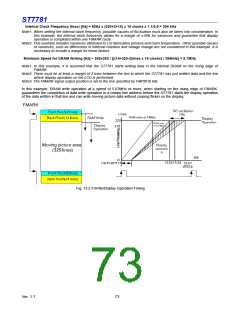
Fig. 13.2.2 Moving Picture Data Transfers via FMARK Function
When transferring data in synchronization with FMARK signal, minimum DRAM data write speed and internal clock
frequency must be taken into consideration. They must be more than the values calculated from the following equations.
Internal clock frequency
(
fosc
Hz
)
×
Hz
= Frame Frequency min .
(
)
[
]
(
DisplayPor ch
(
NL
)
+ FrontPorch
240 × DisplayLin es
BP + DisplayLin es
(
FP
)
+ BackPorch
NL
NL
(
)
BP ))×16
(
clocks × var iance
)
(
RAMWriteSp eed
(
min .
)[
Hz >
]
1
(
FrontPorch
(
FP
)
+ BackPorch
(
)
(
)
− m arg ins
)
×16
(
clocks ×
)
fosc
Note: When RAM write operation is not started immediately following the rising edge of FMARK, the time from the rising
edge of FMARK until the start of RAM write operation must also be taken into account.
Examples of DRAM writes speed and the frequency of the internal clocks are as follows.
Example:
Display size
320 RGB x 240 lines,
320 lines
Total number of lines (NL)
Back/Front porch:
Frame frequency
14/2 lines
60 Hz
Ver. 1.7
72

 SITRONIX [ SITRONIX TECHNOLOGY CO., LTD. ]