ST7781
13. FMARK Function
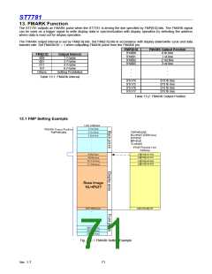
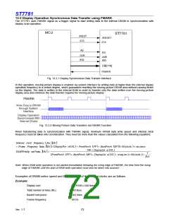
The ST7781 outputs an FMARK pulse when the ST7781 is driving the line specified by FMP[8:0] bits. The FMARK signal
can be used as a trigger signal to write display data in synchronization with display operation by detecting the address
where data is read out for display operation.
The FMARK output interval is set by FMI[2:0] bits. Set FMI[2:0] bits in accordance with display datarewrite cycle and data
transfer rate. Set FMARKOE = 1 when outputting FMARK pulse from the FMARK pin.
FMP[8:0]
9’h000
9’h001
9’h002
9’h003
FMARK Output Position
0 th line
1 st line
2 nd line
3 rd line
FMI[2:0]
000
001
011
101
Output Interval
1 Frame
2 Frame
4 Frame
6 Frame
.
.
.
.
.
.
Others
Setting Prohibited
Table 13.1: FMARK Interval
9’h174
9’h175
9’h176
9’h177
372 th line
373 th line
374 th line
375 th line
Table 13.2: FMARK Output Position
13.1 FMP Setting Example
Fig. 13.1.1 FMARK Setting Example
Ver. 1.7
71

 SITRONIX [ SITRONIX TECHNOLOGY CO., LTD. ]