ST7565S
Display Data Read
This command reads 8-bit data from the specified display data RAM address. Since the column address is automatically
incremented by “1” after the read, the CPU can continuously read multiple-word data. One dummy read is required immediately
after the column address has been set. See the function explanation in “Display Data RAM” for the explanation of accessing the
internal registers. When the serial interface is used, reading of the display data becomes unavailable.
E
R/W
A0 /RD /WR
D7 D6 D5 D4 D3 D2 D1 D0
1
0
1
Read data
ADC Select (Segment Driver Direction Select)
This command can reverse the correspondence between the display RAM data column address and the segment driver output.
Thus, sequence of the segment driver output pins may be reversed by the command. See the column address circuit (page
1–20) for the detail. Increment of the column address (by “1”) accompanying the reading or writing the display data is done
according to the column address indicated in Figure 4.
E
R/W
A0
/RD
/WR
D7 D6 D5 D4 D3 D2 D1 D0
Setting
0
1
0
1
0
1
0
0
0
0
0
1
Normal
Reverse
Display Normal/Reverse
This command can reverse the lit and unlit display without overwriting the contents of the display data RAM. When this is done
the display data RAM contents are maintained.
E
R/W
A0
/RD
/WR
D7 D6 D5 D4 D3 D2 D1 D0
Setting
0
1
0
1
0
1
0
0
1
1
0
RAM Data “H”
LCD ON voltage (normal)
RAM Data “L”
1
LCD ON voltage (reverse)
Display All Points ON/OFF
This command makes it possible to force all display points ON regardless of the content of the display data RAM. The contents
of the display data RAM are maintained when this is done. This command takes priority over the display normal/reverse
command.
E
R/W
A0
/RD
/WR
D7 D6 D5 D4 D3 D2 D1 D0
Setting
0
1
0
1
0
1
0
0
1
0
0
1
Normal display mode
Display all points ON
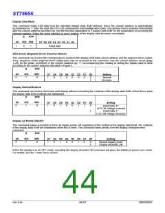
When the display is in an OFF mode, executing the display all points ON command will place the display in power save mode.
For details, see the Power Save section.
Ver 0.6c
44/72
2009/09/07

 SITRONIX [ SITRONIX TECHNOLOGY CO., LTD. ]