ST7565S
COMMANDS
The ST7565S identify the data bus signals by a combination of A0, /RD (E), /WR(R/W) signals. Command interpretation and
execution does not depend on the external clock, but rather is performed through internal timing only, and
thus the processing is fast enough that normally a busy check is not required.
In the 8080 MPU interface, commands are launched by inputting a low pulse to the RD terminal for reading, and inputting a low
pulse to the /WR terminal for writing. In the 6800 Series MPU interface, the interface is placed in a read mode when an “H” signal
is input to the R/W terminal and placed in a write mode when a “L” signal is input to the R/W terminal and then the command is
launched by inputting a high pulse to the E terminal. Consequently, the 6800 Series MPU interface is different than the 80x86
Series MPU interface in that in the explanation of commands and the display commands the status read and display data read
/RD (E) becomes “1(H)”. In the explanations below the commands are explained using the 8080 Series MPU interface as the
example.
When the serial interface is selected, the data is input in sequence starting with D7.
<Explanation of Commands>
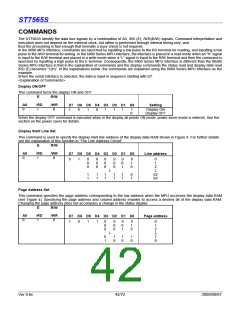
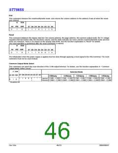
Display ON/OFF
This command turns the display ON and OFF.
E
R/W
A0
/RD
/WR
D7 D6 D5 D4 D3 D2 D1 D0
Setting
0
1
0
1
0
1
0
1
1
1
1
0
Display ON
Display OFF
When the display OFF command is executed when in the display all points ON mode, power saver mode is entered. See the
section on the power saver for details.
Display Start Line Set
This command is used to specify the display start line address of the display data RAM shown in Figure 4. For further details
see the explanation of this function in “The Line Address Circuit”.
E
R/W
A0
/RD
/WR
D7 D6 D5 D4 D3 D2 D1 D0
Line address
0
1
0
0
1
0
0
0
0
0
0
0
0
0
0
0
0
0
0
1
0
1
0
0
1
2
↓
↓
1
1
1
1
1
1
1
1
1
1
0
1
62
63
Page Address Set
This command specifies the page address corresponding to the low address when the MPU accesses the display data RAM
(see Figure 4). Specifying the page address and column address enables to access a desired bit of the display data RAM.
Changing the page address does not accompany a change in the status display.
E
R/W
A0
/RD
/WR
D7 D6 D5 D4 D3 D2 D1 D0
Page address
0
1
0
1
0
1
1
0
0
0
0
0
0
0
0
1
0
1
0
0
1
2
↓
7
8
↓
0
1
1
0
1
0
1
0
Ver 0.6c
42/72
2009/09/07

 SITRONIX [ SITRONIX TECHNOLOGY CO., LTD. ]