ST7565S
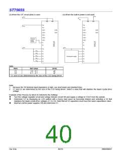
* When the V5 voltage regulator internal resistors or the electronic volume function is used, it is necessary to at least set the
voltage regulator circuit and the voltage follower circuit to an operating mode using the power control set commands. Moreover,
it is necessary to provide a voltage from VOUT when the Booster circuit is OFF.
* The VR terminal is enabled only when the V5 voltage regulator internal resistors are not used (i.e. the IRS terminal = “L”).
When the V5 voltage regulator internal resistors are used (i.e. when the IRS terminal = “H”), then the VR terminal
is left open.
* Because the input impedance of the VR terminal is high, it is necessary to take into consideration short leads, shield
cables, etc. to handle noise.
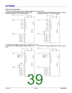
The LCD Voltage Generator Circuit
The V5 voltage is produced by a resistive voltage divider
within the IC, and can be produced at the V1, V2, V3, and V4
voltage levels required for liquid crystal driving. Moreover,
when the voltage follower changes the impedance, it
provides V1, V2, V3 and V4 to the liquid crystal drive circuit.
High Power Mode
The power supply circuit equipped in the ST7565S chips has
very low power consumption (normal mode: HPM = “H”).
However, for LCDs or panels with large loads, this low-power
power supply may cause display quality to degrade. When
this occurs, setting the HPM terminal to “L” (high power
mode) can improve the quality of the display. We recommend
that the display be checked on actual equipment to determine
whether or not to use this mode. Moreover, if the
improvement to the display is inadequate even after high
power mode has been set, then it is necessary to add a liquid
crystal drive power supply externally.
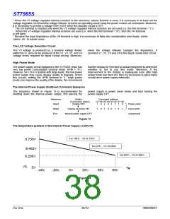
The Internal Power Supply Shutdown Command Sequence
The sequence shown in Figure 13 is recommended for
shutting down the internal power supply, first placing the
power supply in power saver mode and then turning the
power supply OFF.
Sequence
Step1
Details
(Command, status)
Display OFF
Command address
D7 D6 D5 D4 D3 D2 D1 D0
1
0
0
1
1
0
0
1
0
1
1
1
0
0
Power saver
commands
(compound)
Step2
Display all points ON
1
1
End
Internal power supply OFF
Figure 13
The temperature gradient of the Internal Power Supply (-0.05%/°C)
Ta=-40°C , V5=8.735V
8.735V
Ta=25°C , V5=8.460V
8.460V
8.206V
Ta=85°C , V5=8.206V
V5
0V
Ta
-40°C
-20°C
0
°C
25°C
50°C
85°C
Figure 14
Ver 0.6c
38/72
2009/09/07

 SITRONIX [ SITRONIX TECHNOLOGY CO., LTD. ]